
Layout Planner (Beta)
The Layout Planner assembles factory and machine layouts directly in the browser. You work with reusable library objects such as conveyors, robots and fixtures while the 3D scene remains the center of the planning workspace.
Planner mode is for authoring and arrangement rather than machine operation. It adds the library, a planning grid, snapping tools, translation and rotation handles, and compatible snap-point connections.
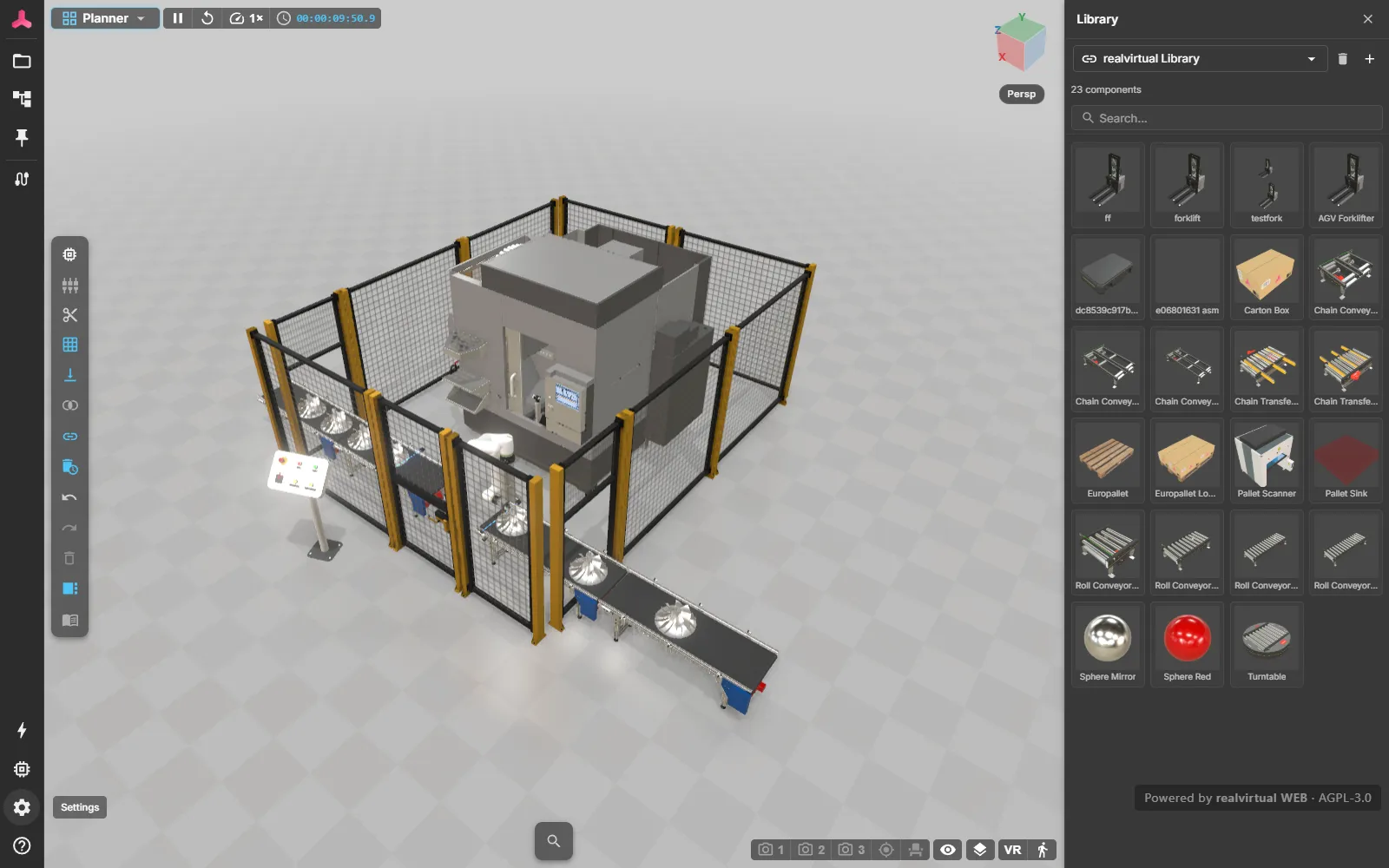
Layout planning is one of the use cases of realvirtual. It starts from a twin built in the Editor or exported from Unity.
Core workflow
Section titled “Core workflow”- Library provides the reusable objects available for the current planning project.
- Placement adds an object from the library to the 3D layout.
- Grid and snapping help you position objects consistently.
- Translate and rotate handles refine the position and orientation of a selected object.
- Snap-point connections align compatible connection points between layout objects.
Try it live: Layout Planner demo.
The library window
Section titled “The library window”The library window lists the sources you can place from, as tabs. The project you are working in is the first tab and the default one — everything you or the Editor saved into it is placeable straight away, with no publishing or registration step in between.
Further tabs appear only for libraries that are explicitly attached: named by the project’s manifest, passed on the URL, or added by you. Nothing is attached because it happened to ship with the build, so the tabs you see are the ones somebody chose.
The standard library, catalogs from a local folder, a remote URL or a GitHub repository, the ?library= parameter and how an object’s pivot is decided are covered under library and catalogs.
Connecting objects
Section titled “Connecting objects”Compatible objects click together through snap points — typed connectors that carry direction, so a conveyor output only mates with a matching input. Connected objects then move as one chain, can be flipped around their connection, and can be locked against accidental edits. See snap points.
Editing transport paths
Section titled “Editing transport paths”The paths that vehicles and material flow travel along are ordinary planner objects — you draw and edit them in the layout instead of preparing them elsewhere.
- Handles. Each vertex of a path, and both of its free ends, is a draggable handle. Arcs get a centre and a radius handle instead; an arc end cannot be dragged freely, because without a tangent constraint that has no single answer.
- The chain never tears. Dragging a vertex that two segments share moves both of them in one step.
- Ends snap. Dragging a free end onto a nearby compatible port connects it — the free end of another path, or a station’s snap point. Direction is respected: the start of a path only accepts outgoing or bidirectional ports, and an occupied port is skipped.
- Undo and redo apply. A finished drag is a normal editing step, so it undoes, redoes and saves like any other change to the layout.
- Editing while it runs is safe. Vehicles already on an edited path are carried over onto the new geometry rather than dropped, and a vehicle waiting at the end stays waiting.
A closed loop has no free ends and therefore no ports to connect to.
Quick Start
Section titled “Quick Start”- Open the Layout Planner demo or a prepared planning link.
- Confirm that Planner is the active workspace.
- Open the Library and choose an object that belongs in the layout.
- Place the object in the scene, then use the translation or rotation handles to position it.
- Enable the required grid or snap behavior and bring compatible snap points together.
- Drag the end of a transport path onto a station’s snap point to connect it, and check the result in the DES workspace.
- Select the placed objects in the hierarchy to review their structure and connections.
See also
Section titled “See also”- Library and catalogs — where placeable objects come from
- Snap points — typed connectors, chain dragging, flipping and locking
- Navigation and controls
- Documents
- Discrete event simulation