
MU Data and Barcodes
MU data lets a part carry information through the plant: a barcode, a serial number, a variant, a pallet ID or a test result. A Source creates parts with start values, a MUDataWriter changes a value at a station, and a BarcodeReader reports it to the PLC like a real scanner. The data is visible as a label next to the part and in the Inspector.
Common use cases
Section titled “Common use cases”- Barcode or serial number – A counter at the loading station gives every part its own number, and a reader further down the line reports it.
- Variant and order data – Parts carry a variant or order number that a controller reads to select the program.
- Pallet tracking – A pallet carries an ID, a type and a status, like an RFID tag on a workpiece carrier.
- Quality state – A station writes a result, and a later reader or the PLC uses it.
Define data fields
Section titled “Define data fields”Add the MUData component to an MU template (the node a Source copies) or to a part you pre-placed in the model. Every part created from the template gets its own copy of the start values.
Select the node, click Add Component in the Inspector and choose MUData. In the Fields list, click Add entry for each field:
| Setting | What it does |
|---|---|
| Name | Letters, digits and underscore, not starting with a digit. Each name is used once per MU. The writer, the reader and the label refer to this name |
| Type | Text, Int, Float or Bool |
| Default | The start value, or Unset. A new field starts unset. An explicit 0, empty text or false is a real value |
| ShowOnLabel | Shows the field on the 3D label of the part. On by default |
A part has at most 32 fields. Text is limited to 256 characters, Int must be a whole number and Float must be a finite number.
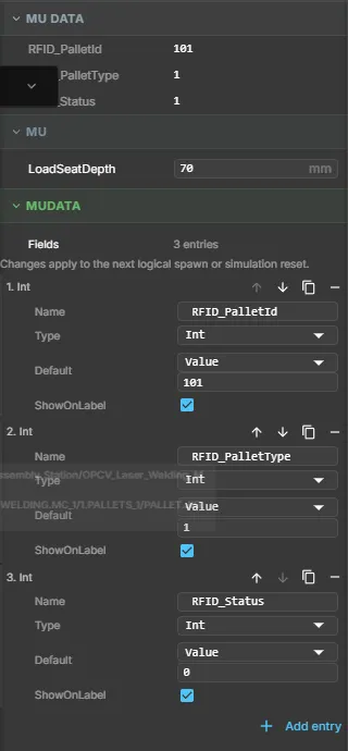
The MU DATA block at the top shows the live values of the selected MU while the simulation runs. An unset field shows as an em dash. The MUDATA block below is the field list. A change there applies to the next part that is created, or after a simulation reset.
Write data (MUDataWriter)
Section titled “Write data (MUDataWriter)”The MUDataWriter writes one field of an MU at a station. Put it on a node that has a Sensor, and point Sensor at it.
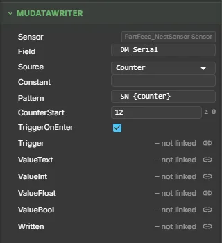
| Setting | What it does |
|---|---|
| Sensor | The station sensor. The writer acts on the MU in this sensor |
| Field | The MU data field to write. The field must exist on the MU, otherwise the Problems panel reports it |
| Source | Where the value comes from: Constant, Signal, Counter or Pattern |
| Constant | The value for Constant, read as the field type (true / false for Bool) |
| Pattern | Text with {counter}, for example SN-{counter}. Used by Pattern |
| CounterStart | First number of the counter for Counter and Pattern. At least 0 |
| TriggerOnEnter | Writes when an MU enters the sensor. On by default |
| Trigger | A PLC output. A rising edge writes the MU that is in the sensor at that moment |
| ValueText, ValueInt, ValueFloat, ValueBool | PLC outputs for Source = Signal. Bind the one that matches the field type |
| Written | A PLC input that pulses for one tick after each write |
The counter advances only after a successful write. A simulation reset sets it back to CounterStart. A text value from a signal is cut to 256 characters.
Read data (BarcodeReader)
Section titled “Read data (BarcodeReader)”The BarcodeReader reads one field of an MU at a station and reports it to the PLC. It works the same for a barcode, a DataMatrix code or an RFID tag.
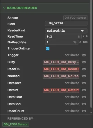
| Setting | What it does |
|---|---|
| Sensor | The station sensor. The reader reads the MU in this sensor |
| Field | The MU data field to read |
| ReaderKind | Barcode, DataMatrix or RFID. A label only: it does not change how the reader works |
| ReadTime | Duration of a read in seconds. Default 0.2 |
| NoReadRate | Share of reads that fail, from 0 to 100 percent. The draw is made at the trigger and repeats with the same simulation seed |
| TriggerOnEnter | Starts a read when an MU enters the sensor. Off by default |
| Trigger | A PLC output. A rising edge starts a read |
A read runs like this:
- A trigger starts the read. Busy is 1, ReadOK and NoRead are 0. A trigger while the reader is busy is ignored.
- After ReadTime of simulation time, the reader checks that the MU is still in the sensor, the field has a value and the no-read draw did not hit.
- If so, the value goes to the data signal that matches the field type and ReadOK is 1. Otherwise NoRead is 1, and a text output is empty.
ReadCount counts the finished reads. The results stay until the next trigger. A field that is declared but unset counts as a normal NoRead.
Signals to the PLC
Section titled “Signals to the PLC”All reader outputs are PLC inputs. The twin writes them and the PLC reads them.
| Signal | Content |
|---|---|
| Busy, ReadOK, NoRead | Bool: read in progress, success, failure |
| DataInt, DataFloat, DataBool | The value of an Int, Float or Bool field |
| DataText | The value of a Text field, as a text signal. Empty on NoRead |
| ReadCount | Number of finished reads |
Bind only the data signal that matches the field type. Text is never converted to a number. See Text signals.
Show data on the part
Section titled “Show data on the part”A part with at least one set field marked ShowOnLabel gets a label next to it. The label lists one Name: value row per field. A part whose fields are all unset has no label.
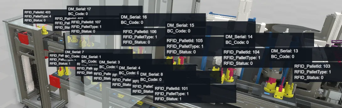
- Switch on and off – The labels are an overlay named MU data labels. It is off by default. Switch it with the MU data labels button in the tool strip, or in the Overlays section of the Display panel. Both use the same setting, which the viewer remembers.
- Only when there is something to show – The button appears only when the loaded model defines data fields shown on labels.
- Select or hover – While the overlay is off, a selected or hovered part still shows its label.
- Loads – A part carried by another part gets its label in its own row above the carrier’s label.
- Distance and number – Labels fade out with distance. At most 64 labels are shown at the same time.
- Inspector – A selected part shows its live values in the MU DATA block. Parts that are drawn as instances for speed show their data on the label only.
Signals and PLC
Section titled “Signals and PLC”The reader signals are normal PLC signals. Create them with the Signals buttons in Quick Edit, and link them to the slots of the component. A connected controller reads them, or a Structured Text program in the browser does. The browser runs the twin locally on your computer, not in a cloud service, so the model and its data stay with you. Text values use STRING and WSTRING variables, see Strings.
With a real Beckhoff controller, a text signal is linked to a STRING(n) or WSTRING(n) symbol. The TwinCAT ADS interface describes the string length and encoding. The MU data fields themselves are not sent to the PLC. Only what a reader reports and what a writer takes from a signal reaches the controller.
Example: Laser Welding Assembly Station
Section titled “Example: Laser Welding Assembly Station”The Laser Welding Assembly Station shows the whole chain on a running line. Open it in the public demo: choose Projects, then Laser Welding Assembly Station. Select a pallet or a valve and look at the MU DATA block, and switch on MU data labels.
- Pallets – Each of the 14 pallets carries
RFID_PalletId,RFID_PalletTypeandRFID_Status. Writers set the status on the way, and RFID readers at the stopper and index stations read the ID. - Valves – A writer at the part feed gives each new valve a
DM_Serialfrom a counter. A DataMatrix reader at station FG01 reads it with a no-read rate of 2 percent. - Barcode – A writer and a barcode reader at the return-conveyor stopper (Stopper02) handle
BC_Code. - PLC – The reader results are PLC inputs for the signal list. The demo is a display of the data: it does not eject a part on a no-read.
Model courtesy of Villette Oh (GrabCAD).
Continuous simulation and DES
Section titled “Continuous simulation and DES”MU data, the writer and the reader work in the continuous simulation. They are not active in a DES run, and the Problems panel says so. In a multiuser session the data is not synchronised, and followers run no writers or readers.
Use it from an AI agent
Section titled “Use it from an AI agent”An agent reads and sets the data of an MU with two commands:
mu.data– reads all fields of the MU withmuId, or one field withfield. An unset field returnsnull.mu.data.set– writes a live value. It takesmuId,fieldandvalueJson, a JSON string, number or boolean that matches the field type.
Call them with web_query and web_execute. A live write does not create an undo step or a macro line.
See also
Section titled “See also”- Signals and Logic – signal types, text signals and logic steps
- MU (Movable Unit) – how parts move through the model
- Material Flow – sources, sinks and conveyors
- Virtual PLC (ST) – read the reader signals in Structured Text
- TwinCAT ADS interface – STRING and WSTRING symbols
- Demo Models – the Laser Welding Assembly Station