
Operator Panel
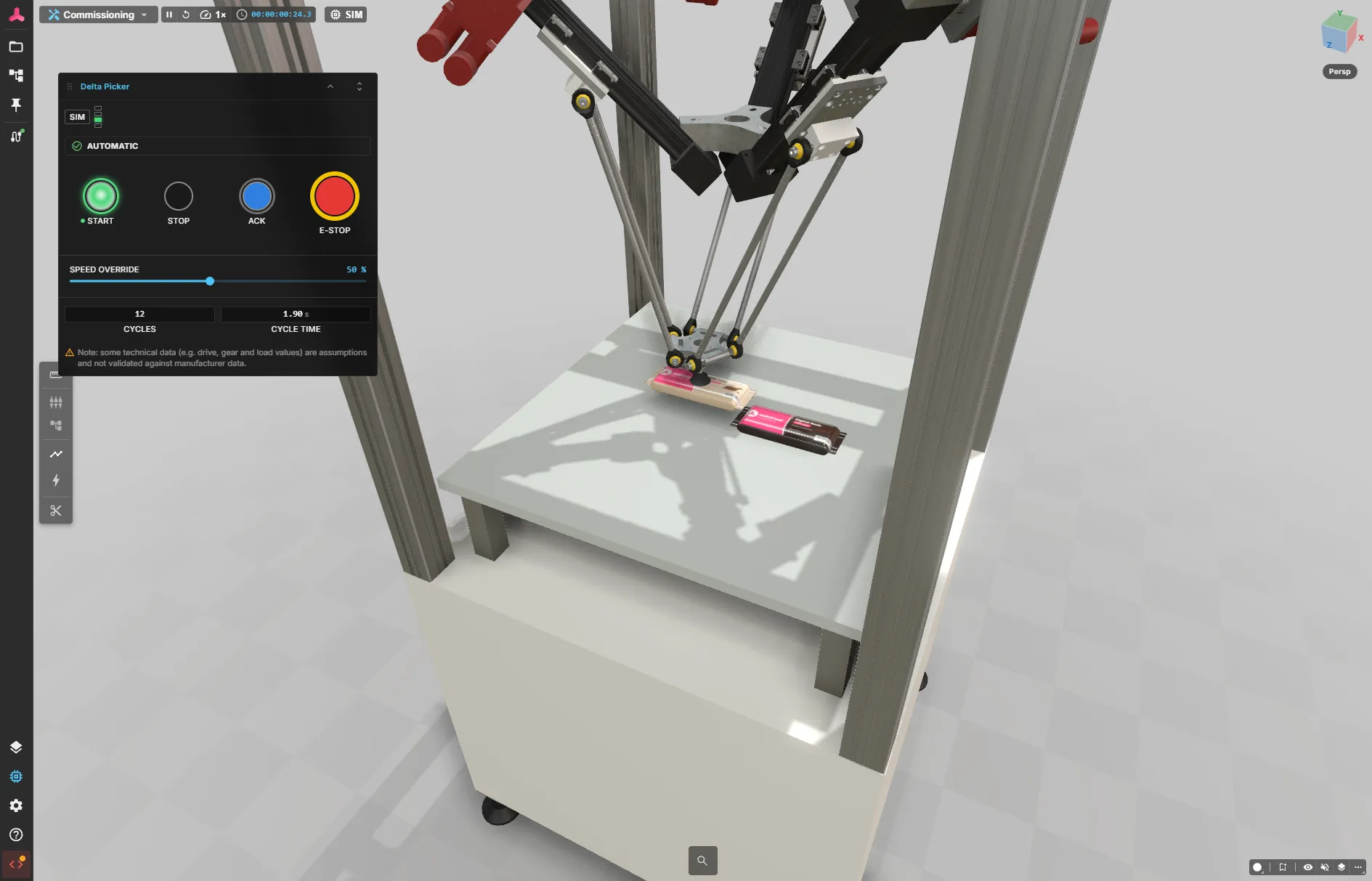
During virtual commissioning the real machine panel does not exist yet. The operator panel takes its place. It shows the machine’s controls next to its 3D model: illuminated push buttons, two-position selector switches, emergency stops, a stack light and a status line. The controls look and behave like those on the real machine.
Each button and switch writes the same PLC input as the real device. Each lamp shows the same PLC output. So you can test the PLC program with operator actions, such as start, stop, acknowledge and E-stop, before the real panel is built.
The panel is stored as data in the model, without code. The viewer opens it in a separate window when the GLB loads. This works for the main model and for every placement of it in a layout.
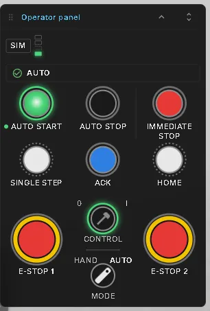
The Laser Welding Assembly Station includes a complete panel. Open it in HMI mode to try the controls on this page.
What is on the panel
Section titled “What is on the panel”| Device | How it behaves |
|---|---|
| Push button | Writes its PLC input while held and releases it when you let go. Its lamp ring shows the connected PLC output |
| Selector switch | A knob or key with two positions, such as Hand / Auto. It stays in the selected position |
| E-stop | A latching mushroom button. Press to latch it; releasing takes a short hold on the pressed button, like twisting a physical E-stop to release it. Press R to release it from the keyboard |
| Slider | A setpoint dial. Dragging it writes a number to a float PLC input while you drag, for example a speed override |
| Readout | A display of one number from a float PLC output, or of two to four numbers as one vector instrument |
| Stack light | A signal tower at the top of the panel, with each segment driven by a PLC output |
| Status line | A message about the machine state, such as AUTO, STOPPED: press AUTO START or FAULT: release E-stop 1 |
| Chips | Short markers at the top of the panel. The first one always shows the control mode: SIM while the virtual PLC runs, PLC with a lock while a real controller is in charge. Further chips come from the panel, such as HAND in manual mode |
Colours follow IEC 60204-1: red for emergency and immediate stop, blue for acknowledge, green or white for start, yellow for intervention. A lamp shows the colour of the output it is wired to, so a black Auto Stop cap can carry a blue lamp.
Every button writes a PLC input and every lamp reads a PLC output. This follows the standard signal convention. The PLC determines what each button does. When no controller is connected, the model’s virtual PLC controls the response.
Testing the PLC with the panel
Section titled “Testing the PLC with the panel”Connect the twin to your controller as described in Connecting a PLC. Then use the panel instead of the real HMI:
- Press the buttons and switches to send the operator signals to the PLC. The controller receives the same inputs as it will from the real panel.
- Watch the lamps and the stack light to see what the PLC outputs do.
- In PLC mode, the real or simulated controller runs the sequence. In SIM mode, the model’s virtual PLC runs it.
Stopping and restarting
Section titled “Stopping and restarting”The status line shows the steps to recover from a fault and counts them.
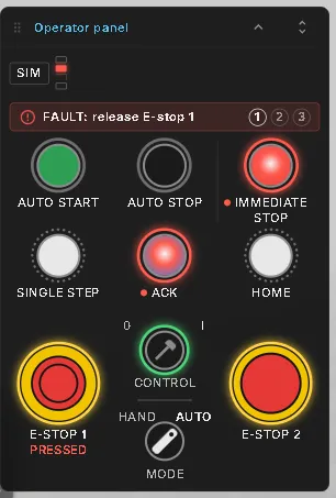
On the welding station:
- Press E-STOP 1. Every axis stops at once and the status line shows a fault.
- Hold the pressed E-stop until its ring fills and the button releases. The status line now asks for ACK.
- Press ACK to acknowledge the fault. The station waits in STOPPED.
- Press AUTO START. Every station continues from where it stopped.
Auto Stop lets the station finish its current work before stopping. Press Auto Start to resume.
Sliders and readouts
Section titled “Sliders and readouts”A slider has a signal, a range (min, max), an optional step (default 1), a unit and the number of decimals. A readout shows a signal (or two to four signals as one vector, with componentLabels), with unit and decimals. Use scale when the signal is in other units than the display, for example 1000 to show a value in metres as millimetres. smoothingMs calms the displayed figure with a low-pass filter in milliseconds; the signal itself stays raw. Both can take more than one grid column with span.
Moving and collapsing the window
Section titled “Moving and collapsing the window”Drag the title bar to move the panel out of the way. The viewer remembers its position.
Click the arrow in the title bar to collapse the panel to its title bar. Click it again to open the panel; the viewer remembers whether it was open or collapsed.
A panel can show quiet guidance below its devices, before the key legend. Use it for hints that are not a machine state, for example to say that the data behind a demo are assumptions. A note has no frame and is not an alarm. It wraps across lines.
| Field | Meaning |
|---|---|
text | The guidance. Required, not blank, at most 200 characters |
tone | info (default) or caution. Caution colours only the small icon amber; the text stays secondary |
icon | info or warning. Optional; by default info for the info tone and warning for the caution tone |
"notes": [ { "text": "Select a mode before starting." }, { "text": "Keep the work area clear.", "tone": "caution" }]Omit notes, or use [], for no guidance.
Adding a panel to your own model
Section titled “Adding a panel to your own model”A panel is a WebOperatorPanel component on any node of the model. Its Config field stores the panel as JSON. This defines the devices, their grid positions, the signals they read or write, the status rules and the restart steps. Every signal name must exist in the model.
Create the configuration in one of three ways:
- In the Editor, add the component to a node and paste the configuration into its Config field. The window appears when the field is valid. Errors appear in the window and the Problems panel.
- Ask an AI assistant through the AI bridge. It lists the model’s signals, builds the configuration and checks the result. Its guide,
web_help("operator-panel"), also contains the welding station’s complete configuration. - Generate it with a build script, like any other component field.
Save the model to keep the panel with it.
A minimal configuration
Section titled “A minimal configuration”This panel has a green Start button with a lamp, a black Stop button and a status line. The signals S_Start, S_Stop and L_Run must exist in the model:
{ "version": 1, "id": "cell-panel", "title": "Cell", "buttons": [ { "label": "Start", "signal": "S_Start", "capColor": "green", "lamp": { "signal": "L_Run", "color": "green" }, "row": 1, "col": 1 }, { "label": "Stop", "signal": "S_Stop", "capColor": "black", "row": 1, "col": 2 } ], "selectors": [], "estops": [], "stackLight": [], "status": [ { "kind": "running", "tone": "ok", "text": "RUNNING", "when": { "signal": "L_Run", "is": true } }, { "kind": "idle", "tone": "neutral", "text": "READY" } ]}version (always 1), id (unique in the model), title, buttons, selectors, estops, stackLight and status are required; the lists may be empty. Each device sits in a grid cell given by row and col (1-based, up to columns, default 3). Devices in the same cell stack on top of each other. A status rule shows its text when its when condition holds; the first rule that holds wins, and a rule without when always holds, so put it last. A condition tests a boolean signal ({ "signal": "L_Run", "is": true }) and can be combined with all, any and not.
The component’s other fields: Title overrides the window title, Dock chooses the corner where the window first appears (when the configuration has no position) and StartCollapsed opens it collapsed.
Command buttons
Section titled “Command buttons”A button can run a simulation command instead of writing a PLC signal. Give it command instead of signal. A button has exactly one of the two; with both or neither, the editor shows an error. The command runs once each time you press the button. There is no hold, and no signal is written, so the button also works while the panel’s signals are missing.
If the command cannot run, the button is greyed out and its tooltip gives the reason. An unknown command id only produces a warning, because the command may be registered later.
This button resets the simulation, like the Reset button in the simulation controls:
{ "label": "Reset", "command": "sim.reset", "capColor": "white", "row": 2, "col": 2 }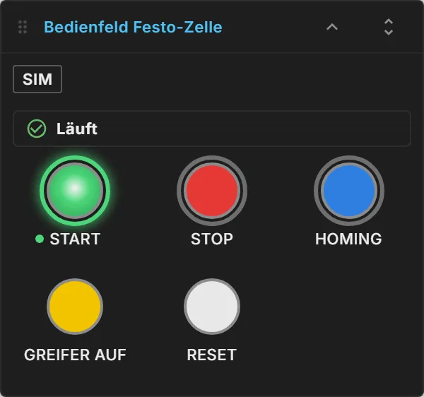
To let a controller reset the simulation through a signal, see Simulation Reset.
Rows and layout
Section titled “Rows and layout”The columns are equally wide and the layout is automatic. Add rows to format the rows that hold devices:
"rows": [ { "row": 1, "align": "center" }, { "row": 2, "align": "center", "divider": "above" }, { "row": 3, "divider": "above", "title": "Readouts" }]| Field | Meaning |
|---|---|
row | The row number, unique and 1-based. The row must hold a device |
align | start keeps the column grid, center centres the occupied cells, spread distributes them across the width. Without it the row aligns automatically |
valign | bottom keeps a common legend baseline, center puts the device faces on one centre line |
divider | none (default), above or below. above row n and below row n-1 are the same line |
title | A heading of up to 40 characters in the divider. A boundary can carry only one title |
width (pixels, default 300) sets the window width. A button with "separated": true gets a hairline on its left edge, for example an immediate stop.
See also
Section titled “See also”- Virtual Commissioning — all commissioning functions at a glance
- Connecting a PLC — CONNECT between the twin and a real or simulated PLC
- Signals & Alarms — the signals behind the buttons and lamps, and the Simulation / PLC switch
- Demo Models — the Laser Welding Assembly Station
- Signal Binding — connecting the model’s signals to a real controller