
Overview
Section titled “Overview”Use MC function blocks to command simulated single axes, straight Cartesian paths and robots. MotionGroup and its child MotionAxis components configure the PLC’s motion task. The task writes position signals; drive behaviours such as Drive_FollowPosition consume those signals. It never directly moves a Drive.
The implemented subset follows PLCopen Motion Control Part 1 v2.0 and Part 4,
with the limits described below. A group of kind Robot couples the motion task to a
RobotIK and commands its joints from the TCP pose (see Robots).
Properties
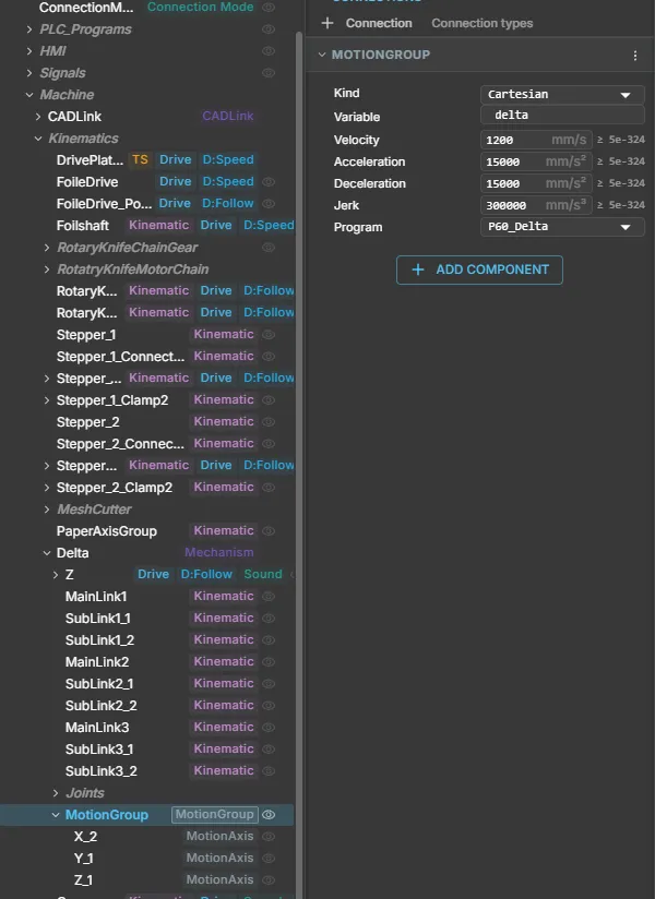
Section titled “Properties”| MotionGroup property | Type / unit | Default |
|---|---|---|
| Kind | enum Cartesian / Robot | Cartesian |
| Kinematics | ComponentReference to a RobotIK (Robot only) | empty |
| JointVelocity | number, deg/s (Robot only) | 120 |
| JointAcceleration | number, deg/s² (Robot only) | 600 |
| JointJerk | number, deg/s³ (Robot only) | 6000 |
| AngularVelocity | number, deg/s (Robot only) | 180 |
| Program | ComponentReference to owning PLCProgram | unbound; required |
| Variable | string, program handle variable name | empty; required |
| Velocity | number, mm/s | 500 |
| Acceleration | number, mm/s² | 5000 |
| Deceleration | number, mm/s² | 5000 |
| Jerk | number, mm/s³ | 100000 |
Profile defaults must be finite and strictly positive. Add MotionAxis components to child nodes; nested groups own their own descendants.
| MotionAxis property | Type / unit | Default |
|---|---|---|
| Name | string; unique X, Y or Z (Cartesian), J1..Jn (Robot) | empty; required |
| Setpoint | PLCOutputFloat signal slot, in the axis unit | unbound; required |
| Feedback | PLCInputFloat signal slot, in the axis unit | unbound; optional |
| Min / Max | number, logical mm | -1000000 / 1000000 |
| Offset | number, mm | 0 |
| Sign | enum 1 / -1 | 1 |
| Variable | string, optional AXIS_REF handle of this axis | empty |
| Unit | enum mm / deg | mm |
Min and Max must be finite with Min < Max. Cartesian axes use Unit = mm, robot axes
Unit = deg; a wrong unit is reported and blocks the deploy. For a Robot group Min, Max
and Offset are hidden and not used: the drive limits of the RobotIK apply. The signal value is
Offset + Sign × logical position; feedback uses the inverse. Without Feedback, readers
use the simulated set-position. A configured invalid feedback produces an error.
The inspector uses the standard reference picker, signal slot rows, selects and number/string editors. Runtime position and command state are read-only. Redeploy after changing motion configuration. The newer fields (Kind, Kinematics, the joint dynamics, MotionAxis Variable and Unit) are taken over at deploy: a change shows “Takes effect on the next PLC deploy” and never affects a move that is running.
Quick start
Section titled “Quick start”- Add a PLCProgram and a MotionGroup.
- Add one to three child MotionAxis nodes, configure coordinate names and bounds, and bind each Setpoint to a PLCOutputFloat position signal.
- Configure each drive’s position-following behaviour to consume the matching signal.
- Enter the program below. Set MotionGroup.Program to that PLCProgram and Variable
to
motion. - Deploy, then Run in continuous simulation. Raise Start after enablement.
PROGRAM PositioningVAR motion : AXES_GROUP_REF; enable : MC_GroupEnable; move : MC_MoveLinearAbsolute;END_VARVAR_EXTERNAL Start : BOOL; END_VAR enable(AxesGroup := motion, Execute := TRUE); move(AxesGroup := motion, Execute := enable.Done AND Start, PositionX := 100.0, PositionY := 50.0, PositionZ := 0.0);END_PROGRAMZero profile inputs select group defaults. Hold Start through completion, then release and raise it for another move. Use AXIS_REF and Axis for a group containing exactly one MotionAxis. Handles belong only in PROGRAM VAR, are required on every MC call and cannot be assigned, calculated or passed through user POUs.
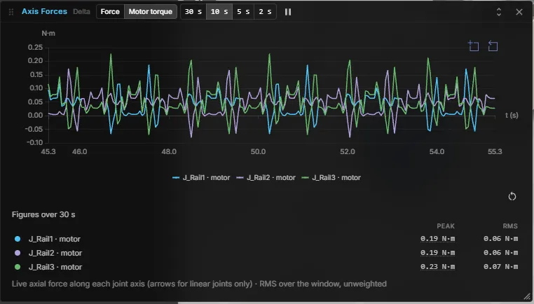
To check the profile on a running machine, open Axis forces for the mechanism and switch to Motor torque. Jerk-limited moves show smooth, repeating peaks without spikes:
Available function blocks
Section titled “Available function blocks”| Single axis | Purpose |
|---|---|
| MC_Power | Level-sensitive logical enable; Status/Valid |
| MC_Reset | Clear a resolved fault at standstill |
| MC_ReadActualPosition | Enable → Valid/Busy/Position |
| MC_MoveAbsolute | Absolute Position |
| MC_MoveRelative | Signed Distance from position at activation |
| MC_MoveVelocity | Continuous Velocity; InVelocity when speed is reached |
| MC_Halt | Interruptible controlled stop |
| MC_Stop | Controlled stop with held-Execute interlock |
| Group (Cartesian or Robot) | Purpose |
|---|---|
| MC_AddAxisToGroup | Add an axis handle to the group before enabling it |
| MC_GroupEnable / MC_GroupDisable | Enable coordination / immediately cancel and hold |
| MC_GroupReset | Clear a resolved fault at standstill |
| MC_MoveLinearAbsolute | Straight move to Position (array) or PositionX/Y/Z (Cartesian only); optional transition to the previous move |
| MC_MoveDirectAbsolute | Point-to-point move to Position; all axes arrive together; optional transition to the previous move |
| MC_GroupHalt | Controlled stop that locks nothing and can be replaced by the next move |
| MC_GroupStop | Controlled stop with held-Execute interlock |
| MC_GroupReadActualPosition / MC_GroupReadPosition | Enable → Valid/Busy/Position[0..5] and PositionX/Y/Z |
Execute commands trigger on a rising edge; falling Execute does not cancel the motion. Call instances cyclically to observe completion. Positional moves expose Done, Busy, Active, CommandAborted, Error and ErrorID. Stop has no Active port; MoveVelocity has InVelocity instead of Done. Readers use Enable, Valid and Busy, plus Error/ErrorID.
Positions and enums. Position is an ARRAY[0..5] OF LREAL, set element by element
(move.Position[2] := 400.0;). A MC_MoveLinearAbsolute instance uses either Position or
PositionX/Y/Z, never both. CoordSystem takes MC_COORD_SYSTEM.ACS (0) or MC_COORD_SYSTEM.MCS
(1, default); BufferMode takes the bare constants mcAborting/mcBuffered or the qualified
enum MC_BUFFER_MODE. MC_MoveDirectAbsolute takes Velocity, Acceleration, Deceleration and Jerk
in percent of the group’s nominal dynamics (0 means 100 %).
Only the first call of one MC instance per scan evaluates inputs; later calls return cached values. Use separate instances for scan-order arbitration. Direction constants are mcPositiveDirection (1), mcShortestWay (2), mcNegativeDirection (3) and mcCurrentDirection (4). Absolute linear moves accept but ignore a valid Direction; MoveVelocity rejects shortest-way. Zero Velocity selects the default, not a stop.
Axis states are Disabled, Standby, DiscreteMotion, ContinuousMotion, Stopping and ErrorStop. Group states are GroupDisabled, GroupStandby, GroupMoving, GroupStopping and GroupErrorStop. Enable reaches standby; completed moves return to standby; faults require reset after the cause clears.
Robots
Section titled “Robots”Set the group Kind to Robot, assign the robot’s RobotIK to Kinematics and add one MotionAxis per
joint named J1 to Jn (the index in the RobotIK axis list) with Unit deg. Bind each Setpoint to the signal
that the joint’s drive follows. The group then commands the robot from poses instead of single coordinates.
PROGRAM PickVAR arm : AXES_GROUP_REF; enable : MC_GroupEnable; toPick : MC_MoveDirectAbsolute; lift : MC_MoveLinearAbsolute;END_VARVAR_EXTERNAL Start : BOOL; END_VAR toPick.Position[0] := 300.0; toPick.Position[1] := -250.0; toPick.Position[2] := 400.0; toPick.Position[3] := 180.0; toPick.Position[4] := 0.0; toPick.Position[5] := 90.0; lift.Position[0] := 300.0; lift.Position[1] := -250.0; lift.Position[2] := 500.0; lift.Position[3] := 180.0; lift.Position[4] := 0.0; lift.Position[5] := 90.0; enable(AxesGroup := arm, Execute := TRUE); toPick(AxesGroup := arm, Execute := enable.Done AND Start, CoordSystem := MC_COORD_SYSTEM.MCS); lift(AxesGroup := arm, Execute := toPick.Done);END_PROGRAMPose contract
Section titled “Pose contract”With CoordSystem = MCS (the default), Position[0..2] is the local X, Y, Z position in millimetres and
Position[3..5] the local rotation as Euler angles X, Y, Z in degrees (order XYZ) of a node that hangs
directly below the RobotIK node and sits on the tool point. These are exactly the numbers the Inspector
shows for such a node (the Inspector shows metres; multiply by 1000). Moving, turning or uniformly
scaling the robot base does not change them. To read the pose of a mark elsewhere in the scene, use
MC_GroupReadPosition or the read-only line Pose in robot frame on the RobotIK.
CoordSystem = ACS takes the joint values J1 to Jn in degrees. MC_MoveDirectAbsolute moves point to
point in either system; MC_MoveLinearAbsolute on a Robot group needs the array form, and with ACS the
joint target is converted to a pose and approached on a straight line. MC_GroupHalt brakes along the path
without locking, MC_GroupStop locks until Execute falls.
Limits of robot motion
Section titled “Limits of robot motion”- The solution nearest to the current joint position is always used; there is no configuration or turn data.
- Only rotary axes; a chain with a linear axis is refused with a diagnostic.
OrientationModesupports onlymcLinear(0): the orientation turns the shortest way, evenly along the line.- A linear move is checked when it becomes active: samples at most 10 mm and 2° apart, at most 2000 (20 m).
An unsolvable sample ends the command with
16#800Fbefore anything moves. At run time a joint jump of more than 30° per step stops the group with16#800F; recover withMC_GroupReset. - The tool rotation is limited by
AngularVelocity; point-to-point moves useJointVelocity,JointAccelerationandJointJerkas 100 %. - A linear move limits the tool dynamics (
Velocity,Acceleration,Jerk,AngularVelocity), not the joint dynamics. Close to a singularity (for example a nearly stretched wrist) the joints can exceedJointVelocity,JointAccelerationandJointJerkeven at a low tool speed. Keep linear moves away from singular poses or lower the tool speed there; use a point-to-point move to pass through. - Blending between moves works as described under Blending between moves. Only
ACSandMCS; the robot IK solver must be loaded (otherwiseMC_GroupEnableanswers16#800D).
Blending between moves
Section titled “Blending between moves”By default a move ends at standstill before the next one starts. MC_MoveLinearAbsolute and MC_MoveDirectAbsolute
can instead pass a corner without stopping: the group leaves the first move shortly before its end, follows a smooth
curve and joins the second move. realvirtual WEB runs locally, so the curve is planned on your machine with no cloud
service and your data stays with you.
The three inputs belong to the second move (the successor) and describe the transition from the first move into it:
| Input | Values | Meaning |
|---|---|---|
TransitionVelocity | MC_TRANSITION_VELOCITY: mcTVZero 0, mcTVLow 1, mcTVPrevious 2, mcTVNext 3, mcTVHigh 4 | Speed in the curve. mcTVZero (default) stops at the corner as before. 1 uses the lower of the two move velocities, 2 that of the first move, 3 that of the second, 4 the higher one |
TransitionMode | MC_TRANSITION_MODE: mcTMNone 0 (default) or mcTMCornerDistance 3 | Only these two modes execute; mcTMStartVelocity, mcTMConstantVelocity and mcTMMaxCornerDeviation give 16#8004 |
TransitionParameter | ARRAY[0..3] OF LREAL | [0] is the corner distance d: millimetres on a linear move, degrees of the leading joint on a point-to-point move, millimetres on the linear move of a mixed pair. [1..3] are reserved and must be 0 |
A transition needs BufferMode = mcBuffered, TransitionVelocity other than 0, TransitionMode = mcTMCornerDistance
and a successor that is commanded while the first move is still running. With mcAborting, or with the inputs at
their defaults, the first move brakes as before. The reference point is fixed to the start of the second move.
A value of 0 or less for d, a TransitionVelocity outside 0 to 4 or a nonzero TransitionParameter[1..3] returns 16#8004.
PROGRAM CornerVAR arm : AXES_GROUP_REF; enable : MC_GroupEnable; first, second : MC_MoveLinearAbsolute; corner : ARRAY[0..3] OF LREAL;END_VARVAR_EXTERNAL Start : BOOL; END_VAR first.Position[0] := 300.0; first.Position[1] := -250.0; first.Position[2] := 400.0; first.Position[3] := 180.0; first.Position[4] := 0.0; first.Position[5] := 90.0; second.Position[0] := 500.0; second.Position[1] := -250.0; second.Position[2] := 400.0; second.Position[3] := 180.0; second.Position[4] := 0.0; second.Position[5] := 90.0; corner[0] := 40.0; enable(AxesGroup := arm, Execute := TRUE); first(AxesGroup := arm, Execute := enable.Done AND Start); second(AxesGroup := arm, Execute := enable.Done AND Start, BufferMode := MC_BUFFER_MODE.mcBuffered, TransitionVelocity := MC_TRANSITION_VELOCITY.mcTVLow, TransitionMode := MC_TRANSITION_MODE.mcTMCornerDistance, TransitionParameter := corner);END_PROGRAMWhat is blended
Section titled “What is blended”- Linear to linear, point-to-point to point-to-point and mixed pairs, on robot groups and on Cartesian groups.
- The corner distance is limited to half the length of the shorter of the two moves. The Problems panel then shows
the info
motion-blend-distance-capped. - The speed in the curve is never higher than the limits allow: the joint limits along the curve,
AngularVelocityand the speed from which the second move can still stop at its end. - Stop, Halt, an Aborting command or a fault inside the curve brake along the path.
When the group stops at the corner
Section titled “When the group stops at the corner”No transition arises, and the group stops at the corner exactly as without blending, when
- the second move is commanded too late, for example in the scan in which the first move already reaches the corner,
- the curve cannot be driven within the limits,
- the check of the second move uses up its budget or the second move is unreachable,
- the group is already braking, or the pair has no curve (a pure rotation, a move of length zero),
- a move is longer than 20 m (2000 samples).
The Problems panel then shows the info motion-blend-rejected with the reason, once per program run. Both hints are
reported at the end of the scan. The second move is checked over its stopping distance when it is accepted and step by
step ahead of the motion. If that check fails before the curve starts, the transition is dropped and the second move
ends with 16#800F when it starts; once the curve has started, the group stops with 16#800F and brakes inside the
checked part.
Limits
Section titled “Limits”- A linear move limits the tool dynamics, not the joint dynamics (see Limits of robot motion). At a transition the joint limits hold in the sense “not worse than without a transition”; close to a singularity the joint jerk can lie slightly above its limit.
- Only
mcTMCornerDistanceexists. The obsoletemcBlendingLowtomcBlendingHighbuffer modes stay rejected with16#8007; useTransitionVelocityinstead.
Ownership and lifecycle
Section titled “Ownership and lifecycle”A group has exactly one owning PLCProgram occurrence. Many FB instances can share its handle, but one handle cannot bind two groups. Missing/duplicate bindings and competing program/group or group/group set-point writers refuse deployment with Problems entries.
Live controller values override local motion; the task writes nothing to live-bound or forced set-points. Authority loss suspends the group until authority returns and it is reset. Reconnect resynchronises without replaying commands. External operation/jog must enter the PLC as signals.
Runner Stop, scan error, COLD redeploy and group removal brake and hold under local authority. Simulation/PLC Reset is immediate, even while paused, and clears motion before the viewer resets drives. Power off/GroupDisable cancel immediately; use Stop first for a controlled stop.
Errors, limits and use cases
Section titled “Errors, limits and use cases”| ErrorID | Meaning |
|---|---|
| 16#8001 | Invalid binding |
| 16#8002 | Disabled |
| 16#8003 | Axis bounds exceeded |
| 16#8004 | Invalid parameters |
| 16#8005 | Owner/writer conflict |
| 16#8006 | Forced/external authority |
| 16#8007 | Invalid BufferMode/Direction |
| 16#8008 | State/interlock refusal |
| 16#8009 | Invalid feedback |
| 16#800A | Profile provider failure |
| 16#800B | Axis of another group added |
| 16#800C | Axis added twice, or group enabled before all axes were added and powered |
| 16#800D | Robot kinematics unavailable (reference missing, solver not loaded, no solver budget) |
| 16#800E | Point-to-point target unreachable |
| 16#800F | Linear path not solvable or jump guard hit |
| 16#8010 | Coordinate system not supported |
These are realvirtual-specific positive DINT values. Parameter errors reject that request without disturbing healthy motion. Kernel faults latch ErrorStop/GroupErrorStop.
Use this subset for Cartesian handling, positioning, single-axis speed control and robots with rotary axes. Only ACS and MCS exist as coordinate systems; homing and synchronisation are absent, and moves are blended only with the corner distance transition. Acceleration/deceleration share the conservative limit min(A,D). Every replacement brakes first, including a collinear move. Done reports profile completion, with no hardware settling monitor. An unavailable protected profile core uses a warned trapezoid fallback without a jerk guarantee.
Continuous simulation and DES
Section titled “Continuous simulation and DES”PLCopen motion runs in both simulation kinds. In DES the moves advance on a fixed motion cycle, and the program scans only when something it reads changes.
| Continuous simulation | DES (event-driven) | |
|---|---|---|
MC_ blocks | Run; the motion task advances the profile every simulation step | Run; a fixed motion cycle (the Cycle Time of the DES manager) advances the profile while a move is running |
| When a command starts | In the same simulation step, right after the scan that issued it | At the following motion cycle point, up to one cycle later |
| When the program scans | Every step | When a command’s status or InVelocity changes, and on its other triggers (signal change, timer, own change). A program that reads a position with MC_ReadActualPosition or MC_GroupReadActualPosition also scans when that axis moves |
| Idle model | Scans every step | No motion cycle events while no move is running |
| DES check | Not applicable | MC_ blocks cause no finding. D5 remains only for a motion program started without the DES motion cycle |
| Snapshots | Not applicable | A move that is running when you save continues identically after the restore |
| End position and timing | Reference | The same profile, started on the motion cycle grid. Do not expect the same timestamps as in continuous simulation |
A snapshot is refused, with the reason shown before it is saved, in two short situations: a move was started before the DES run began (let it finish), or a motion task is still braking after its program or group was removed (try again after about a second).
Robots in DES
Section titled “Robots in DES”Robot groups run in DES as well: MC_MoveDirectAbsolute and linear moves use the same motion cycle, and a snapshot taken during a robot move continues identically after the restore. The IK solver must be loaded when you restore.
With a limited number of live IK solves, a model that contains both a PLC-controlled robot group and an IK path cannot be saved as a snapshot. The snapshot menu shows the reason before saving, and loading such a snapshot is refused without changing the running simulation. With an unlimited solver budget, or with only PLC robot groups or only IK paths in the model, snapshots work.