
Virtual PLC (Structured Text)
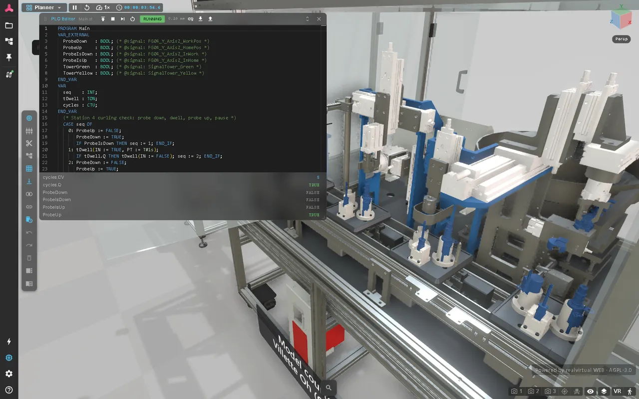
The virtual PLC runs a Structured Text (ST) program directly in the browser. Write the program in the PLC editor, click Deploy and Run, and it scans once per simulation tick: it reads the twin’s PLC signals, runs your logic and writes the outputs. Nothing has to be built or installed — the program is compiled in the browser the moment you deploy it.
Use it to test control logic against the twin before the real controller exists, to try out a sequence quickly, or to teach PLC programming on a running machine. For simple sequences without code, use logic steps instead.
Quick start
Section titled “Quick start”- Switch to the Planner workspace and click the PLC Editor button in the tool bar on the left.
- If the model already has PLC programs, the editor opens the first one. Otherwise the model gets a node PLC with a PLC Program component and a short template program.
- Edit the program. Syntax errors are marked while you type.
- Click Deploy to compile and load the program. Compile errors and unknown signals appear as markers in the code.
- Click Run. The status changes to running and the watch list shows live values.
The editor stays open when you change to another workspace, and the PLC keeps running — like a real controller, while you watch the plant. Only the Viewer workspace hides the editor.
Editor controls
Section titled “Editor controls”| Control | What it does |
|---|---|
| Deploy | Compiles the program and loads it with fresh timers, counters and memory |
| Run / Stop | Starts cyclic scanning, or stops it. Stop keeps all values, so Run continues where it stopped |
| Step | Runs exactly one scan — useful while the simulation is paused |
| Reset | Resets timers, counters and memory to their start values |
| Status | stopped, running or error. Hover the status to read the error message. The scan time in ms is shown next to it |
| Insert signal | Opens a signal browser and inserts the chosen signal into the program (see below) |
| Export / Import | Saves the program as a .st file, or loads one |
| Program list | In a model with several programs: every program in scan order with its state and scan time. Pick one to edit it |
The watch list below the code shows the current values of all signals the program uses and the outputs of its timers and counters, such as tDwell.Q or cycles.CV. Hover a name in the code to see its type, value and signal.
Connecting signals
Section titled “Connecting signals”A program reaches the twin through a VAR_EXTERNAL block. By default the variable name is the signal name:
VAR_EXTERNAL SensorInFeed : BOOL; (* reads the signal SensorInFeed *) ConveyorStart : BOOL; (* writes the signal ConveyorStart *)END_VARTo use a short name in the program, or a signal whose name is not a valid ST name (for example FG01_P_Camera.bReady), add the signal name as a comment:
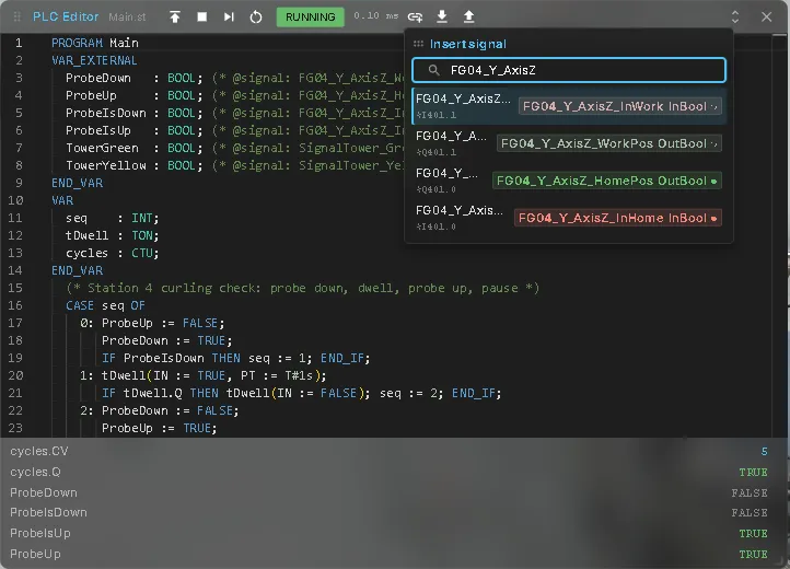
VAR_EXTERNAL ProbeDown : BOOL; (* @signal: FG04_Y_AxisZ_WorkPos *)END_VARInsert signal writes these lines for you. Search for a signal and pick it; the editor adds the declaration with a short name and the @signal comment and inserts the name at the cursor. The browser lists the model’s signals and the signals of a connected realvirtual CONNECT interface, with direction, type and address.
When you deploy:
- A signal the program only reads but that does not exist gets a warning and reads
FALSEor0. Usually the name has a typo. - A signal the program writes but that does not exist is created under
PLC/<name>.
Example: station 4 of the welding station
Section titled “Example: station 4 of the welding station”This program for the Laser Welding Assembly Station moves the probe of the curling check down and up and switches the yellow tower light on after five cycles:
PROGRAM MainVAR_EXTERNAL ProbeDown : BOOL; (* @signal: FG04_Y_AxisZ_WorkPos *) ProbeUp : BOOL; (* @signal: FG04_Y_AxisZ_HomePos *) ProbeIsDown : BOOL; (* @signal: FG04_Y_AxisZ_InWork *) ProbeIsUp : BOOL; (* @signal: FG04_Y_AxisZ_InHome *) TowerGreen : BOOL; (* @signal: SignalTower_Green *) TowerYellow : BOOL; (* @signal: SignalTower_Yellow *)END_VARVAR seq : INT; tDwell : TON; cycles : CTU;END_VAR CASE seq OF 0: ProbeUp := FALSE; ProbeDown := TRUE; IF ProbeIsDown THEN seq := 1; END_IF; 1: tDwell(IN := TRUE, PT := T#1s); IF tDwell.Q THEN tDwell(IN := FALSE); seq := 2; END_IF; 2: ProbeDown := FALSE; ProbeUp := TRUE; IF ProbeIsUp THEN seq := 3; END_IF; 3: tDwell(IN := TRUE, PT := T#2s); IF tDwell.Q THEN tDwell(IN := FALSE); seq := 0; END_IF; END_CASE; cycles(CU := seq = 3, R := FALSE, PV := 5); TowerGreen := TRUE; TowerYellow := cycles.Q;END_PROGRAMThe welding station’s own program Station04 drives these outputs too. To try the example there, pick Station04 in the program list and Stop it first, then deploy and run your program.
Virtual PLC and logic steps
Section titled “Virtual PLC and logic steps”The virtual PLC runs independently of a model’s logic steps. If both write the same outputs, they work against each other — you have to resolve that in the model yourself.
Several programs
Section titled “Several programs”A model can carry several PLC programs, one PLC Program component per node — like the blocks of a real PLC, one per unit of the machine. All of them scan in the same tick, one after another in the order set by their Order field. An output written by two programs is reported as a conflict.
The Laser Welding Assembly Station is controlled this way: eleven programs under the node PLC_Programs — operating modes, transport, the two lifts, the buffer, the entry and the five stations.
Simulation or PLC mode
Section titled “Simulation or PLC mode”A program can read the model’s control mode through the read-only system variable RV_SimulationMode:
VAR_EXTERNAL RV_SimulationMode : BOOL; (* TRUE = Simulation, FALSE = a real PLC owns the outputs *)END_VARA program that reads it steps aside on its own when a real controller takes over: write nothing while it is FALSE. When the model switches to PLC, the outputs of such programs go back to their start values once, so no simulated command — a running belt, an open valve — is left behind. The welding station’s programs all work like this.
A program that does not read RV_SimulationMode keeps writing in PLC mode and works against the real controller. Stop it before you connect one.
Language
Section titled “Language”The PLC supports a practical subset of IEC 61131-3 Structured Text. Keywords are not case-sensitive; comments are written (* … *) or // ….
| Area | Supported |
|---|---|
| Program | One PROGRAM … END_PROGRAM with VAR and VAR_EXTERNAL blocks |
| Statements | :=, IF / ELSIF / ELSE, CASE (single integer labels and ELSE), FOR … BY, WHILE, REPEAT … UNTIL, function block calls with := parameters |
| Types | BOOL, INT, DINT, REAL, TIME |
| Literals | 123, 1.5, 16#FF, TRUE / FALSE, T#2s, T#500ms, T#1m30s |
| Operators | + - * /, MOD, = <> < <= > >=, AND OR XOR NOT |
Not supported yet: strings, arrays, structures, your own functions or function blocks, EXIT / RETURN, CASE ranges, bit operations on integers and => output parameters. The compiler reports them as errors instead of running something unexpected.
Function blocks
Section titled “Function blocks”| Block | Inputs → outputs | What it does |
|---|---|---|
| TON | IN, PT → Q, ET | On-delay: Q turns on after IN has been on for PT |
| TOF | IN, PT → Q, ET | Off-delay: Q turns off PT after IN turns off |
| TP | IN, PT → Q, ET | Pulse of length PT on a rising edge of IN |
| CTU | CU, R, PV → Q, CV | Counts up on each rising edge of CU; Q when CV ≥ PV |
| CTD | CD, LD, PV → Q, CV | Counts down from PV; Q when CV ≤ 0 |
| CTUD | CU, CD, R, LD, PV → QU, QD, CV | Up/down counter |
| R_TRIG / F_TRIG | CLK → Q | Q for one scan on a rising / falling edge |
| RS / SR | S, R1 → Q1 / S1, R → Q1 | Reset-dominant / set-dominant flip-flop |
Timers run on simulation time: when you pause the simulation, timers pause too.
How a scan works
Section titled “How a scan works”The PLC scans once per simulation tick (60 times per second). Each scan reads all inputs at once, runs the program from top to bottom and then writes all outputs together — like the process image of a real PLC. Outputs act on the drives in the same tick.
Resetting the simulation resets every program — timers, counters, memory — and sets its outputs back to their start values, the values they had when the model was loaded.
If a scan runs too long (more than 50 ms, for example an endless loop), uses too much memory or hits an error such as a division by zero, the PLC stops with the status error. Fix the program and click Run again; the PLC restarts with fresh values.
Saving and sharing
Section titled “Saving and sharing”Each program is stored in the model, on its PLC Program component. Changes are saved with the model and can be undone. In a project you cannot write to — such as the public demo — use Export to keep your program as a .st file and Import it again later.
A program whose Active field is set starts by itself when the model is loaded, in every workspace — like the controller of a real machine. With Active off, the program is only loaded into the editor, and Deploy and Run are up to you. Programs run in an isolated sandbox inside the browser and can only read and write signals.
See also
Section titled “See also”- Virtual Commissioning — all commissioning functions at a glance
- Signals and Logic — PLC signals and logic steps
- Signals & Alarms — the Simulation / PLC switch
- Laser Welding Assembly Station — the demo used above
- realvirtual CONNECT — connect a real controller instead