
Quick Edit Reference
Use Quick Edit, on the right of the Editor, to add axes, drives, conveyors, sensors, signals and sequences to a CAD model. This reference follows the order of the sections in the panel.
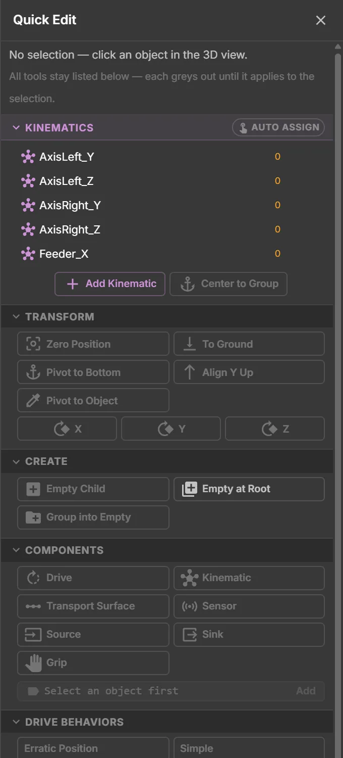
These rules apply throughout the panel:
- Every function stays visible. A button is greyed out if it does not apply to the selection. Hover over it to see why, for example Select an object first, Add a Drive to this object first or Already has a Drive.
- Every change is one undo step. Click Undo in the toolbar to reverse it. The only exception is jogging in Drive Test, which is a preview.
- Nothing can be edited during a test run. Stop the run before editing. Changes made during a run would be lost when it stops.
When you select a signal node, transform and create functions act on its parent. New signals appear next to the selected signal.
To add an axis and drive to a CAD file, follow Your First Twin from CAD.
Kinematics
Section titled “Kinematics”A kinematic is an axis node that groups parts which move together. Its pivot defines where they turn or slide. The list shows the asset’s axes as a tree, with a part count for each axis.
| In the list | What it does |
|---|---|
| Click a row | Selects the axis and makes it the target for Auto Assign |
| Hover a row | Highlights its parts in 3D |
| Count badge | Shows the number of assigned parts. An amber 0 means the axis has no parts yet; no group means its group name is empty |
| Eye / isolate | Hides the axis’s parts, or shows only them. This view setting is never saved |
| Filter box | Finds axes by name |
| Button | What it does |
|---|---|
| Add Kinematic | Creates an empty axis node at the top level (Kinematic, Kinematic_1, …) and makes it the Auto Assign target. It does not use the selection. Assign parts afterwards |
| Add to Kinematic (K) | Adds the selected parts to an axis. Choose an existing axis from the menu, or choose New kinematic… and enter a name. A new axis includes the selected parts. Also available by pressing K in the 3D view |
| Center to Group | Moves the pivot of the selected axis to the centre of its parts. The parts stay where they are |
To assign many parts, turn on Auto Assign in the section header. Click an axis row to select a target, or create one with Add Kinematic. Click parts in 3D or drag a box around them to add them to the target.
The target’s parts are hidden while you work, so you can select the remaining parts. Click another axis to change the target. Press Esc to turn Auto Assign off.
A part can belong to only one axis. Assigning it to another one moves it.
The parts move under the axis in the hierarchy when the asset is loaded, either in a test run or after saving and reopening. Until then, they stay in their original hierarchy positions and the axis cannot be jogged in Drive Test.
Groups
Section titled “Groups”A group is a named set of parts. Hide, isolate or highlight them together, or assign materials to the set. Nothing moves because of a group. A kinematic adds an axis and a drive to a group.
| In the list | What it does |
|---|---|
| Click a row | Selects all parts of the group and makes it the Auto Assign target |
| Chevron | Lists the members; × removes a single member |
| ⊖ | Removes the selected parts from the group |
| ✎ or double-click | Renames the group. Axes that use the group follow the new name |
| 🗑 | Removes the group membership and keeps the parts |
Click Add Group, then enter a name. The new group becomes the Auto Assign target. It is stored in the asset only after you add its first member.
Transform
Section titled “Transform”| Button | What it does | Needs |
|---|---|---|
| Zero Position | Sets the local position to 0, 0, 0 | One or more objects; acts on all of them |
| To Ground | Lifts or lowers the object until its lowest point rests on the floor | One object |
| Pivot to Bottom | Moves the pivot to the bottom centre of the object’s children; the children stay in place | An object with children and no mesh of its own |
| Align Y Up | Turns the object so its local Y axis points up; the children keep their position | An object with children and no mesh of its own |
| Pivot to Object | Click another part to move the pivot to that part’s centre | One object without a mesh of its own |
| Pivot to Circle | Click a part, then a round edge on it. The pivot moves to the circle’s centre, with its Y axis along the circle’s axis. The readout identifies the circle, for example Ø 40.0 mm · cylinder end · shaft | One object without a mesh of its own, typically an axis node |
| X / Y / Z | Rotates by +90° around the local axis; Shift-click turns −90° | One object |
Every pivot tool changes only the pivot. The node moves while its children stay in place. The 3D view looks unchanged.
Press Esc to go back a step in Pivot to Circle. Right-click or click empty space to leave the tool. See Pivot to Circle for step-by-step instructions.
Create
Section titled “Create”| Button | What it does | Needs |
|---|---|---|
| Empty Child | Creates an empty node under the selection | A selected object |
| Empty at Root | Creates an empty node at the top of the asset | — |
| Group into Empty | Creates a node named Group next to the first selected object and moves all selected objects into it, keeping their position | One or more objects |
Use empty nodes for structures missing from the CAD model, such as an axis separate from a part, a holder for signals or a sequence container.
Components
Section titled “Components”A component gives a node a function. Click a button to add a component with default settings. To edit its fields, double-click the node in the hierarchy to open the property inspector.
Each component is described in detail in the Components section. Use ADD COMPONENT at the bottom of the property inspector to add components without a Quick Edit button, such as Lamp, Web Sensor or Zone.
| Button | What it adds | Fields to look at first |
|---|---|---|
| Drive | A motor that moves the node and everything below it, with linear or rotary motion. Defaults to Linear X | Direction (LinearX/Y/Z, RotationX/Y/Z), TargetSpeed (mm/s or °/s), UseLimits with LowerLimit / UpperLimit, Acceleration |
| Kinematic | The axis marker on its own. Usually not needed because Add Kinematic and K create it with its group | GroupName, IntegrateGroupEnable |
| Transport Surface | A conveyor surface that carries parts across the node’s geometry, at the speed of a drive on the node or above it | TransportDirection, DriveReference (only when the drive is elsewhere), Accumulate |
| Sensor | A detector that reports when a part is inside the node’s bounds, or crosses a ray | UseRaycast, RayCastLength (mm), signal slots SensorOccupied / SensorNotOccupied |
| Source | Creates parts. By default the node itself is the part that gets copied | GenerateIfDistance (mm), Interval (s), LimitNumber, PlaceOnTransportSurface |
| Sink | Removes parts that reach it | DeleteMus, DeleteOnlyTag |
| Grip | A gripper that picks and places parts | GripRange (mm), OneBitControl, PlaceMode |
| Box Collider | A box for sensors and physics. On a mesh it is created as a child node Collider | center, size (m). Drag the face handles in 3D to resize; Shift snaps to 5 mm |
| Physics Zone | Turns physics on in a box-shaped region of the model | Friction, Restitution, RemoveBelowY |
Click Add to group (no kinematic) at the bottom to add the selected parts to a plain group. It suggests names from existing groups.
Components cannot be added to logic-step nodes. Each node accepts only one component of each kind. Adding a second Drive shows Already has a Drive.
How the material-flow components work together
Section titled “How the material-flow components work together”- The Source creates a part and drops it onto the Transport Surface below it.
- The transport surface moves the part at the speed of its drive. The drive turns the belt instead of moving its own node.
- A Sensor along the route switches its signal while a part is inside it. Sensors detect parts, not machine geometry.
- The Sink removes the part when it reaches the sink’s footprint, at any height.
The Laser Welding Assembly Station in the demo uses all four.
Drive Behaviors
Section titled “Drive Behaviors”A drive moves at its target speed when commanded. A behaviour reads PLC signals to control when and how the drive moves, as a real actuator would. Add a behaviour to a node that already has a Drive.
A drive takes one behaviour that moves it. The Editor rejects a second one and names the existing behaviour in the tooltip. Position Switch only reads the position, so it can be added next to any other behaviour.
| Behaviour | Typical use |
|---|---|
| Simple | A motor with forward and backward signals, such as a conveyor or jog axis |
| Cylinder | A pneumatic cylinder with two end positions and Out / In signals, plus end-position feedback |
| Destination Motor | A servo axis that moves to a destination on a start signal. Missing signals are created automatically |
| Continous Destination | Like Destination Motor, but a new destination value starts the move without a start bit |
| Speed | A motor whose speed comes from a signal |
| Follow Position | An axis whose position follows a signal directly, such as the output of an FMU |
| Gear | A second axis coupled to a master drive, following it at a set ratio |
| Position Switch | Switches a signal while the axis is inside given position ranges |
| Erratic Position | Moves randomly between two positions for demos and testing |
| SEWMovilink, Profidrive Speed, Profidrive Pos, Festo FHPP, Uni Drive Motor, Proportional Valve | The drive profiles of real devices, with their control and status words |
A behaviour’s signal slots in the property inspector define which signals it reads and writes. Click Link signal for each slot, or drag a signal onto it. See Signal Binding.
Colours
Section titled “Colours”A colour field, such as a signal lamp’s OnColor, shows a swatch and hex value in the property inspector. Click the swatch to choose a colour. Closing the picker saves the value as one undo step and preserves transparency.
Signals
Section titled “Signals”| Button | What it does |
|---|---|
| Out Bool / Out Int / Out Float | Creates a PLC output under the selection. The controller writes this value and the twin reads it |
| In Bool / In Int / In Float | Creates a PLC input. The twin writes this value and the controller reads it |
| To Bool / To Int / To Float | Changes the data type of the selected signal |
| To Input / To Output | Flips the direction of the selected signal |
A new signal is a child node named after its type. Rename it to match its PLC tag.
Signals cannot be placed directly on a node with a Drive, a Kinematic or a logic step. Put them on a plain child node, such as an empty node named Signals. See Signals & Alarms for the direction convention.
Logic Steps
Section titled “Logic Steps”Logic steps form the model’s virtual PLC and run sequences without a controller. For example, a sequence can start a drive, wait for a sensor, set a signal, wait and repeat.
- Select an empty node and click LogicSteps Container. A top-level container repeats its steps in a loop.
- With the container selected, click a step. It is added inside the container, as its last step.
- Select a step, then click the next step to insert it immediately after the selected one. Steps run in hierarchy order.
- Double-click a step in the hierarchy to open its property inspector. Choose its target from the list: the Sensor for Wait Sensor, the drive for Drive To or the Signal for Set Signal. The list shows only matching parts in this asset.
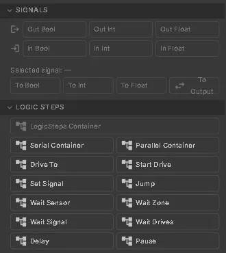
| Step | What it does |
|---|---|
| Serial Container / Parallel Container | Runs its children one after another, or all at once |
| Drive To | Moves a drive to a destination and waits until it arrives |
| Start Drive | Starts the same move without waiting |
| Set Signal | Sets a Boolean signal |
| Wait Sensor | Waits until a sensor is occupied or free |
| Wait Zone | Waits until a zone is occupied, or free |
| Wait Signal | Waits for a signal level, rising edge or falling edge |
| Wait Drives | Waits until a list of drives has reached its targets |
| Jump | Jumps to a named step of the same container when a Bool signal has the value set in JumpOn |
| Delay | Waits a number of seconds |
| Pause | Currently has no effect in realvirtual |
The same list appears for the other references Quick Edit creates: a Grip’s pick and place signals, the master drive of a Gear behaviour and the drive of a Transport Surface. Choose — none — to clear a reference.
The Wait Drives step takes a list of drives. Set the list through an AI assistant connected over the AI bridge.
Mechanism (Rigid-Body)
Section titled “Mechanism (Rigid-Body)”Use this section for closed-loop mechanisms whose joints are solved together, such as a four-bar coupler, scissor lift or delta robot. The section is closed by default. See Rigid-Body Mechanisms for details.
Drive Test
Section titled “Drive Test”Jog the selected drive while you edit, without starting a test run.
| Control | What it does |
|---|---|
| ◀◀ / ■ / ▶▶ | Jog backward, stop at the current position or jog forward |
| ↺ | Puts the axis back where it was before you jogged |
| Position | The current position in mm or ° |
| Speed | The drive’s target speed, saved with the asset |
Jogging is a preview. It resets before saving and creates no undo entry. It is unavailable for:
- A drive added since the asset was last loaded. Start a test run, or save and reopen the asset.
- A drive with a behaviour, because signals control the behaviour.
- A Virtual drive.
- A transport surface’s drive.
Testing
Section titled “Testing”Click the green ▶ next to the workspace selector to start a test run. The asset runs exactly as it would be saved, including drives, signals, sources, sensors and logic steps.
Use the inspector’s Jog − / Jog + buttons to move drives during the run. The run controls offer pause, reset and speed. Click the red ■ to stop the run and restore the editing state exactly as it was.
See also
Section titled “See also”- Editor overview — the workspace, testing and saving
- Your First Twin from CAD — a first axis on a real CAD file
- Signal Binding — linking signals to slots
- Rigid-Body Mechanisms