
IO Modules
In a real cabinet you find a signal fault with the LEDs on the IO cards. The IO modules window brings that tool into realvirtual. It shows the cards of your controller as a flat 2D picture, sorted by slot, with one LED per channel. The window opens next to the 3D model, like the operator panel.
An IO card is a component, WebIOModule, on a node of the model. Nothing is drawn in 3D. The component stores which signal each channel shows, and the window reads the live values.
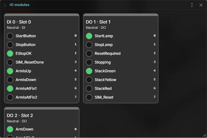
What the LED shows
Section titled “What the LED shows”The LED always shows the value on the controller side of the card. That is what makes a fault findable: the simulated fault sits between the card and the field.
| Card kind | Signal type | LED and display |
|---|---|---|
| DI (digital input) | PLC input, bool | The value the PLC reads, including a fault on the line |
| DO (digital output) | PLC output, bool | The value the PLC program wrote, even if a fault keeps it from reaching the machine |
| AI (analog input) | PLC input, float or int | A bar and the number the PLC reads |
| AO (analog output) | PLC output, float or int | A bar and the number the PLC wrote |
Example: a training scenario holds the output ArmDown at false. The PLC program sets it, so the LED of the DO card lights up, and the arm still does not move. Students conclude that the fault is behind the card, not in the program.
Add a card
Section titled “Add a card”- Select the node that should carry the card, or create an empty node.
- In the Inspector choose Add component and pick WebIOModule.
- Set Kind, Slot and Style and give the card a Label, for example
-A2. - Under Channels add one row per channel and pick the signal with the reference picker. The picker only offers signals that fit the Kind; a wrong type is shown as an error at the field.
| Property | Description |
|---|---|
| Label | Name printed on the card, for example -A2 |
| Kind | DI, DO, AI or AO |
| Slot | Position in the window, counted from 0. Cards are sorted by slot |
| Style | Look of the card: ET200SP, BeckhoffEL or Neutral |
| Channels | One row per channel with Source (signal), ChannelLabel, LedColor and, for AI and AO, RangeMin and RangeMax in the unit of the signal |
The card does not store an address. If a CONNECT gateway maps the signal to a controller address, the window shows that address live. Without CONNECT it shows the channel number.
Generate cards from signals
Section titled “Generate cards from signals”Instead of adding each card by hand, use Generate from signals in the Inspector of a WebIOModule. It reads all signals of the document, groups them by direction and type, and creates the cards with 8 channels each (16 on request). The whole run is one undo step.
AI and macro users call the same function as the command ioModule.generateFromSignals with the argument channelsPerModule set to 8 or 16.
Force a channel
Section titled “Force a channel”In the normal (teacher) view you can click an LED of a DI or DO channel to force the signal, and click again to release it. This uses the same force as the signal list, including its confirmation. In the student view the LEDs are display only.
See also
Section titled “See also”- Training scenarios for signal faults and the student view
- Operator panel for machine controls next to the model
- Signals and alarms