
Signals & Alarms
Signals connect the visible twin to machine state. In a standalone model, simulated sensors, drives and logic provide the values. In Live mode, an industrial interface or realvirtual CONNECT discovers PLC signals and exchanges values with the running machine.
realvirtual presents signal values in the hierarchy, component information, CONNECT panel and signal search. A delivered HMI can also combine those values with configured status indicators, alarm messages, KPIs and documentation.
PLC signal convention
Section titled “PLC signal convention”realvirtual uses Boolean, integer and floating-point signals with an explicit direction. The direction follows the PLC convention:
| Signal | Meaning in realvirtual | Typical use |
|---|---|---|
| PLCInputBool / Int / Float | The viewer writes the value and the PLC reads it | Sensor state, axis feedback, an operator command sent to the controller |
| PLCOutputBool / Int / Float | The PLC writes the value and the viewer reads it | Motor or valve command, lamp, status or counter from the controller |
Read it as the PLC’s terminal strip: a PLC input is something the field — here the digital twin — supplies, and a PLC output is something the PLC drives and the twin shows.
The displayed signal name comes from the model or the connected controller. A signal can also retain its full hierarchy path so the twin can resolve the correct component when names repeat.
Signal display and connection status
Section titled “Signal display and connection status”- A signal chip can show its name, direction, type and current value, depending on the selected display level.
- Hovering a chip can reveal the full signal details, source and component bindings.
- For an active Boolean value, green identifies a PLCOutput and red identifies a PLCInput. These colors describe signal direction, not connection state.
- An inactive or otherwise non-active value is grey. An amber force marker identifies a signal whose value is currently forced or overridden.
- Connection and binding information is shown separately where the active workspace provides it. A lost connection can reconnect automatically when that option is enabled; confirm that Live mode is connected before acting on a displayed value.
Finding a signal
Section titled “Finding a signal”Open the Hierarchy and set its filter to Signals to list every signal in the model. The list shows names, directions and live values side by side, like a PLC tag list.
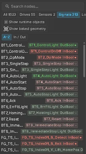
The Laser Welding Assembly Station uses the same signal names as the real station’s TIA tag list. PLC programmers can find each tag by its familiar name during commissioning. Of its 213 signals, 193 are these TIA tags; the other 20, starting with SIM_, are helper signals of the virtual PLC.
Simulation or PLC
Section titled “Simulation or PLC”A model with a virtual PLC made of logic steps can run on its own logic or on a real controller. The Connection Mode component in the model sets which one it starts with.
While an interface is connected and the simulation runs, the Viewer and Commissioning workspaces show the current mode as a small button to the right of the simulation controls:

| Shown | What runs the machine |
|---|---|
| SIM | The model’s virtual PLC writes the PLC outputs; the twin runs on its own |
| PLC | A real controller is expected to write the outputs; the model’s logic steps stay off |
| PLC in green | A connected interface writes the model’s outputs and has taken over. The button is locked until it disconnects |
Click the button to change between SIM and PLC; hover it for the full description. The document saves your choice.
Without a connected interface the button is hidden and the model runs in its saved mode. An AI assistant connected over the AI bridge can still switch it with web_sim_mode. The Operator Panel shows the mode in its first chip at all times.
A connected controller takes over automatically when it writes the first output. When it disconnects, the model returns to the saved mode. The same model can run as a laptop demo or as a commissioning twin connected to a real PLC, without editing it between uses.
Plant behaviour, such as doors or an E-stop chain, keeps running in both modes. The mode stops logic steps; a Structured Text program steps aside only if it reads RV_SimulationMode, otherwise it runs until you stop it in the PLC editor.
Alarms and machine status
Section titled “Alarms and machine status”Alarm and status presentation is configured with the delivered twin. Supported HMI content includes alarm dashboards, messages, drive and sensor states, KPI overlays and production charts. A configured alarm can provide operator guidance or open the associated diagnosis and documentation workflow. Do not assume that every standalone GLB contains an alarm list or live data connection.
Quick Start
Section titled “Quick Start”- Open the twin in its HMI workspace and identify whether it is running in standalone or Live mode.
- Select a component and inspect its signal chips or status indicators.
- Hover a signal chip to review its name, direction, type, source and current value.
- In Live mode, confirm that the connection and binding status indicate live data before acting on a value.
- If the twin provides alarms or messages, open the relevant entry and follow the supplied component, document or diagnosis context.
See also
Section titled “See also”- Virtual Commissioning — all commissioning functions at a glance
- Signal binding — connecting a PLC signal to a component slot
- Operator Panel — buttons, lamps and E-stops wired to these signals
- Documents
- CONNECT overview
- AI diagnosis