
Connecting a PLC
For virtual commissioning the digital twin takes the place of the machine: the PLC runs its real program, and instead of motors, valves and sensors it is wired to the twin. realvirtual CONNECT is the link between the two. It runs on a PC in the controller network, talks to the PLC in its own protocol and exchanges the signals with realvirtual in the browser.
The signal loop
Section titled “The signal loop”In virtual commissioning signals flow in both directions:
| Direction | Signal type | Example |
|---|---|---|
| PLC → twin | PLC Output — the PLC writes, the twin reads | A valve command moves a cylinder, a motor output starts a conveyor, a lamp output lights the stack light |
| Twin → PLC | PLC Input — the twin writes, the PLC reads | A sensor detects a part, a cylinder reports its end position, an operator button is pressed |
Monitoring a running machine only needs the first direction. Virtual commissioning needs both — the PLC only gets through its sequence when the twin’s sensors answer it. The second direction is therefore what distinguishes a commissioning set-up, and it has to be enabled explicitly (step 5 below).
What you need
Section titled “What you need”- realvirtual CONNECT on a Windows PC that reaches the PLC over the network — or, for PLCSIM Advanced, on the PC where PLCSIM Advanced is installed. See Installation.
- A model with PLC signals named like the PLC tags. The Laser Welding Assembly Station is an example: its 193 signals carry the names of the station’s TIA tag list.
- A license for the signal count. The free tier serves up to 20 signals; a real machine usually needs a commercial license. See Licensing.
Step by step
Section titled “Step by step”- Open the viewer through CONNECT. Open
http://localhost:5100on the CONNECT PC, or use Open realvirtual WEB in the tray menu. A hosted viewer can use the local gateway as well — see where the viewer comes from. - Load the model and switch to the Commissioning workspace.
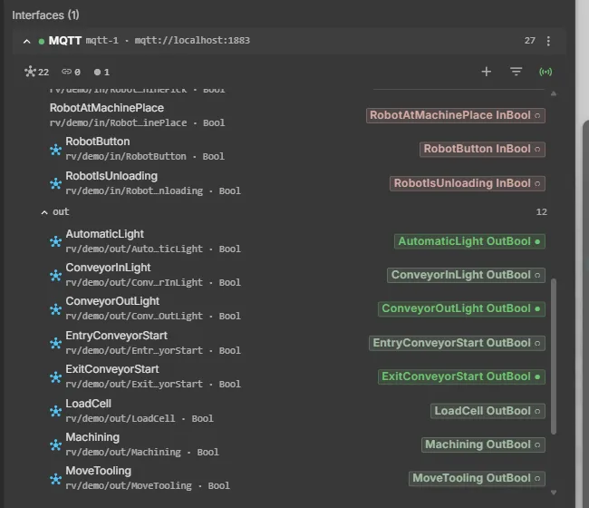
- Add an interface for your controller in the CONNECT panel — for example Siemens PLCSIM Advanced (native API), Siemens S7, TwinCAT ADS or OPC UA — and enter its connection parameters. The card shows Connected once the controller answers. Parameters per controller: Supported protocols.
- Add the signals. Use Browse on the live connection or on a symbol table (for example a TIA
.sdfexport), or import a tag table. Keep the tag names as signal names: the twin binds by name, soFG04_Y_AxisZ_WorkPosin the PLC meetsFG04_Y_AxisZ_WorkPosin the model. Check the direction of each signal — PLC inputs as PLCInput, PLC outputs as PLCOutput. Most browsers derive it from the memory area. See Configuring interfaces. - Allow write access. Turn on Allow web to PLC on the interface. It is off by default; without it the twin’s sensor values and operator buttons stay in the gateway and never reach the PLC. See Write access.
- Let the PLC take over. As soon as the PLC writes the first of the model’s outputs, the model changes to PLC — the button in the top bar turns green and locks, and the model’s logic steps stop. Plant behaviour such as doors or an E-stop chain keeps running. A Structured Text program that reads
RV_SimulationModesteps aside as well and its outputs go back to their start values; one that does not keeps writing — Stop it in the PLC editor before you connect the controller. See Simulation or PLC. - Check the loop. Signals that are bound show a link icon in the CONNECT panel and a green dot when values arrive. Press a button on the Operator Panel and watch the PLC react; force a sensor to test a single reaction.
When the interface disconnects, the model returns to its saved mode and the virtual PLC — logic steps and mode-following ST programs — takes over again.
Controller-specific requirements
Section titled “Controller-specific requirements”| Controller | What to prepare | Details |
|---|---|---|
| Siemens PLCSIM Advanced (native API) | PLCSIM Advanced V4–V7 installed on the CONNECT PC and the instance running. No PUT/GET, no absolute addresses, Softbus works. Tags are addressed by symbol name | PLCSIM Advanced |
| Siemens S7-1200/1500 (real CPU) | PUT/GET allowed in the CPU protection settings; optimized block access disabled for the data blocks you address | Siemens S7 |
| Beckhoff TwinCAT | An AMS route from the PLC back to the CONNECT PC. TwinCAT does not need to be installed on the CONNECT PC | TwinCAT ADS |
| OPC UA server | The endpoint of the server; the nodes the twin writes must be writable | OPC UA |
Further controllers and robot controllers — Modbus, EtherNet/IP, MELSEC, ctrlX, KUKA, FANUC, ABB RobotStudio and others — are listed under Supported protocols.
Switching between simulation and PLC
Section titled “Switching between simulation and PLC”One model serves both: without a controller it runs on its own logic steps, with a controller connected the PLC takes over automatically. Nothing has to be edited in the model between the two uses.
To alternate between several set-ups — for example PLCSIM Advanced in the office and the real CPU on site — save each interface configuration as a CONNECT profile and switch profiles in the CONNECT settings or the tray menu. A profile can also be bound to the model’s document, so opening the document brings up the right configuration. See Profiles.
When it does not work
Section titled “When it does not work”| Symptom | First thing to check |
|---|---|
| The interface does not connect | Network, address and the controller-specific requirements above |
| The model does not move | The signal names on both sides, and the direction of the PLC outputs |
| The PLC does not see sensors or buttons | Allow web to PLC, the direction of the PLC inputs, and on a real CPU the hardware configuration of the inputs |
| Outputs jump between two values | A Structured Text program that does not read RV_SimulationMode is still running — stop it in the PLC editor |
| Only some signals update | The license limit — signals beyond it are listed in the license status |
More: Troubleshooting.
See also
Section titled “See also”- Virtual Commissioning — all commissioning functions at a glance
- realvirtual CONNECT — the gateway in detail
- First connection — CONNECT set-up for monitoring
- Signals and Logic — PLC signals and logic steps in the model