
Your First Twin from CAD
A CAD model is a tree of parts, usually named by part number, with no movement. This guide uses a STEP model of an Autonox DELTA robot to create an asset with a working axis. Every step happens in the browser. The CAD file never leaves your machine.
Follow along in the public demo with any STEP file of your own. The demo has the full editor and needs no account. The only limit is 25 MB per STEP file.
1. Open the import dialog
Section titled “1. Open the import dialog”Open this link:
https://web.realvirtual.io/demo/?doc=new&mode=editorThe link creates an empty asset, switches to the Editor and opens the import dialog. Use the same parameters with your own deployment’s address. To open the dialog from the editor, click Import in the left toolbar.
2. Import the STEP file
Section titled “2. Import the STEP file”Select the STEP tab, keep the defaults and choose your file.
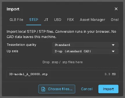
- Tessellation quality — Use Standard for a first try. Choose a coarser setting for very large assemblies, or a finer one if small radii look faceted.
- Up axis — Z-up is the usual CAD convention. If the model arrives lying on its side, import again with Y-up.
Click Import. Conversion runs locally. A 3 MB file appears in the scene after a few seconds. Press Shift+F to frame the whole model.
3. Clean up what CAD brought along
Section titled “3. Clean up what CAD brought along”Open the Hierarchy (left toolbar) and the Quick Edit panel (right). The hierarchy shows the original CAD assembly structure and part numbers.
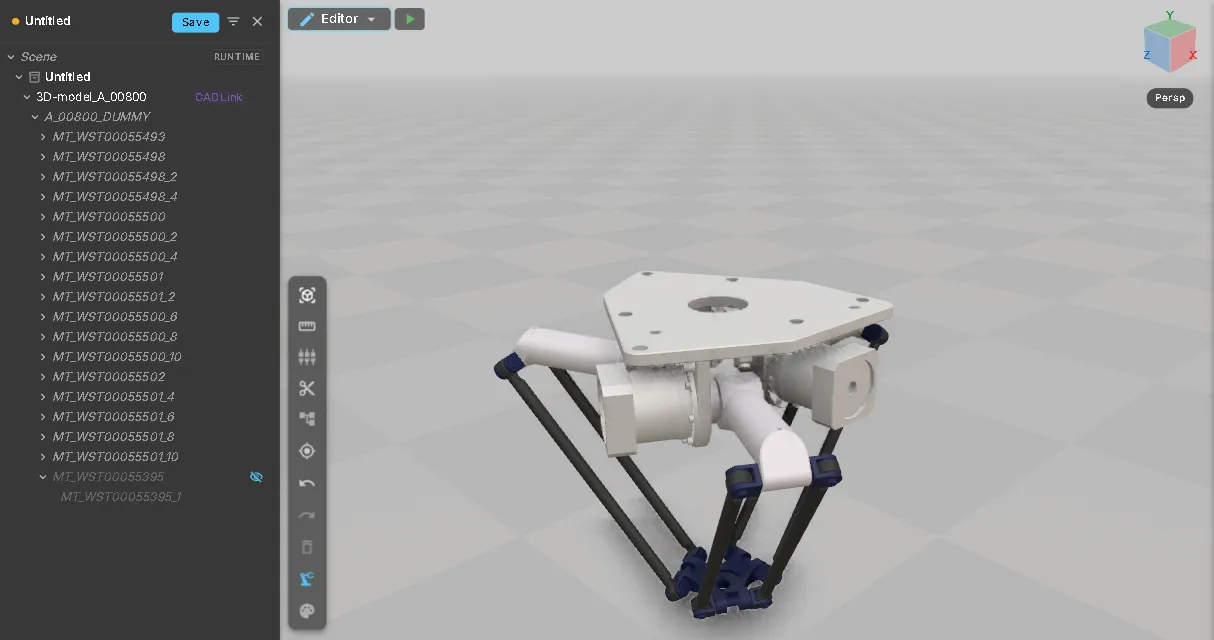
Most CAD imports need these two steps:
- Remove helper geometry. Manufacturer models often include geometry that is not hardware. The DELTA file contains its work envelope as a solid: the large disc that hides the robot after import. Click it in 3D to find its node (here
MT_WST00055395). Select that node in the hierarchy and click Delete. To keep a part but hide it, use the eye icon in the hierarchy. - Fix the orientation. This robot is modelled hanging from its base plate, so it arrives upside down. Select the root node, click the X rotation in Transform twice (180°), then To Ground.
Each action is an undo step. Click Undo in the toolbar to reverse it.
4. Create a rotary axis
Section titled “4. Create a rotary axis”An axis is a Kinematic: a node that groups the parts moving together and defines the point they turn around.
- Click the part that moves. Here, select one upper arm of the robot.
- Click Add to Kinematic (or press K), type a name such as
UpperArm1and confirm. Quick Edit now lists the axis with 1 part. - Put the pivot on the shaft. Click Pivot to Circle, click the arm, then move the cursor over the round edge of the hub where the arm sits on the gearbox. When the circle lights up, click it.
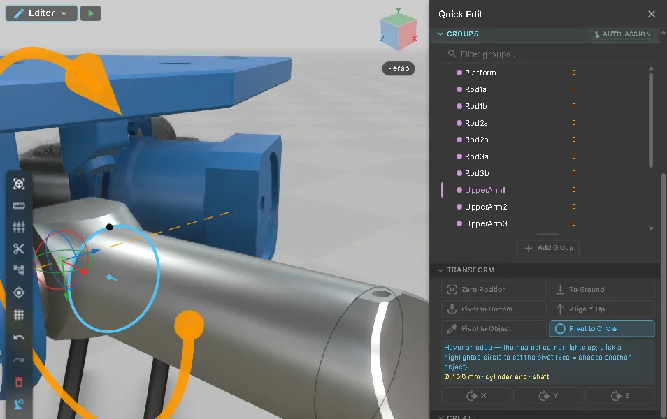
The pivot rarely matches the part origin in CAD. Selecting a bore or shaft is faster and more precise than typing coordinates. See Pivot to Circle for details.
5. Give the axis a drive
Section titled “5. Give the axis a drive”With the axis selected, click Drive under Components. Double-click the axis in the hierarchy to open its property inspector. Set Direction to the rotation around the shaft, here RotationZ.
The dashed line through the pivot shows the rotation axis. The orange arrow shows the direction.
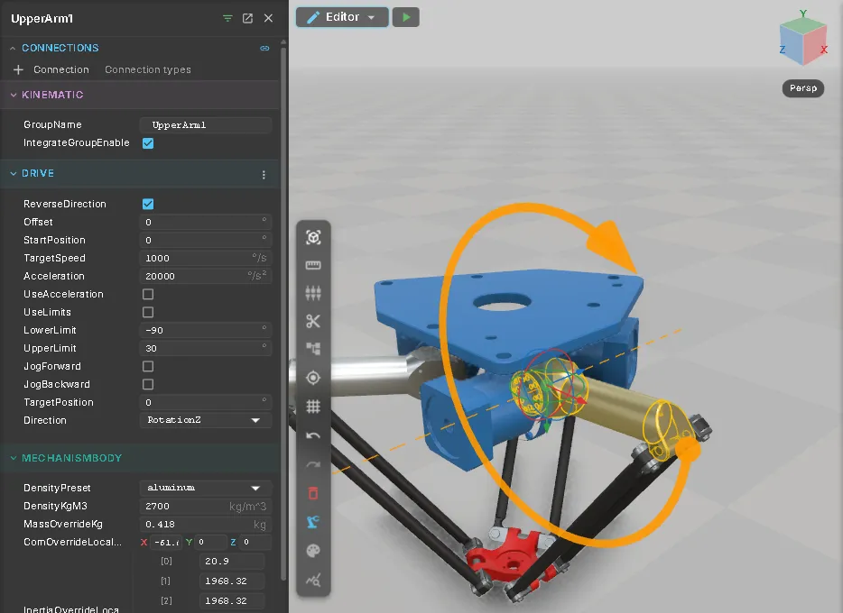
Target Speed, Acceleration and the limits use degrees for a rotary axis. The defaults are fine for a first test.
6. Test it
Section titled “6. Test it”Click the green Start test run button next to the workspace selector. The editor runs the asset exactly as it would be saved and shows the run controls and the simulation clock. Double-click the axis in the hierarchy and use Jog + / Jog − and Stop in the inspector.
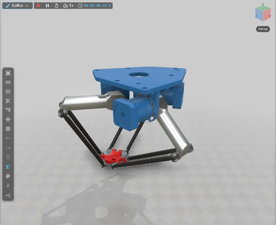
Outside a test run, the Drive Test section at the bottom of Quick Edit jogs the selected axis as a preview and puts it back before you save.
A wrong pivot makes the arm orbit instead of turning. A wrong direction makes it slide instead of swinging. Click the red Stop button in the run controls to restore the editing state exactly as it was before the run.
With one axis, only that arm moves. The rods stay in place because a delta robot is a closed loop.
The screenshots show the finished asset. All three upper arms are axes like this one. A rigid-body mechanism moves the rods and the plate with them. For a conveyor, slide or turntable, a single axis is enough.
7. Save
Section titled “7. Save”Click Save in the document header. This saves the asset as a GLB with its realvirtual metadata in the open project. In the demo, this is My Workspace in the browser.
Place the saved asset in the Layout Planner, connect it to live signals, or reopen it to add the next axis.
Where to go next
Section titled “Where to go next”- Add the other axes the same way, or let Auto Assign in Kinematics propose a structure for the whole tree.
- Build a Twin with AI — have an AI assistant do these steps for you, verifying each axis by moving it.
- Materials — replace the CAD colours with industrial presets.
- Signals and logic — connect the drive to a PLC or a standalone sequence.
See also
Section titled “See also”- Importing CAD — every import source, its settings and the re-import of a newer revision
- Editor overview — Quick Edit, testing and saving in detail
- Quick Edit Reference — every function of the panel, including sensors, sources, signals and logic steps
- Mesh and structure — renaming, grouping and splitting the imported tree
- What You Get — which features are open source and which are commercial