
First Connection
Three things have to come together before a browser shows live machine data: a model to look at, an interface that talks to the controller, and signal names that match on both sides. This page walks the shortest path through all three.
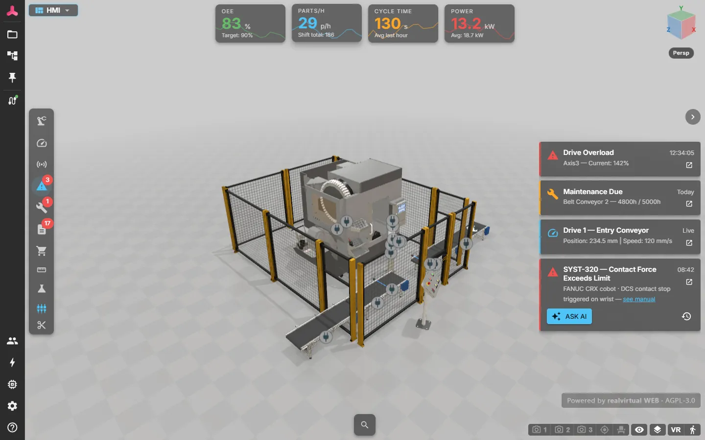
1. Open the HMI
Section titled “1. Open the HMI”Right-click the tray icon and choose Open realvirtual WEB, or open http://localhost:5100.
The bundled viewer is served by the gateway itself — the same origin, so no configuration, no CORS setup and no second web server. It connects to the signal channel automatically and shows the connection state in the CONNECT panel.
A hosted viewer works just as well: a realvirtual deployment on your own server, or the public demo, can talk to the gateway on the operator’s machine. See where the viewer comes from.
2. Load a model
Section titled “2. Load a model”A model is a GLB file that carries geometry and realvirtual metadata together. You get one in two ways:
- From Unity — export or publish with Tools > realvirtual > Export > WebViewer Tools. Publishing into the gateway’s
models/folder updates a running gateway without restarting it. - From CAD — import a STEP or JT assembly directly in the viewer. Files too large for a browser tab are converted by the gateway, see CAD conversion.
Models placed in the gateway’s data folder appear in the viewer’s model list.
3. Add an interface
Section titled “3. Add an interface”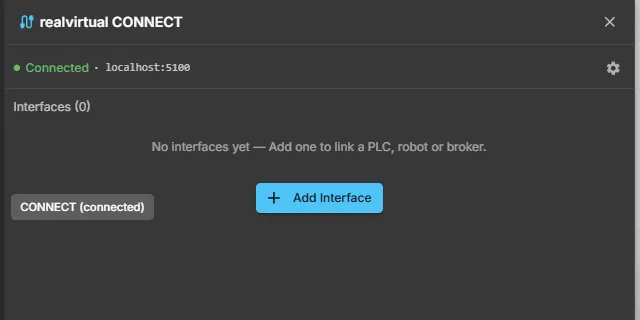
In the viewer, open the CONNECT panel and add an interface:
- Choose the interface type — see supported protocols for the parameters each one needs.
- Enter the connection parameters (address, port, rack/slot, broker URL, credentials).
- Save. The gateway starts the interface immediately and shows its state on the interface card.
A connected interface reports Connected; a failing one shows the reason and retries with a growing backoff — 1, 2, 4, 8, 15, 30 seconds — until it succeeds.
4. Add signals
Section titled “4. Add signals”Signals are what actually travels. Depending on the protocol you get them in one of three ways:
| Way | When |
|---|---|
| Browse | The controller can be browsed — OPC UA, MQTT, ctrlX, TwinCAT, EtherNet/IP, Keba, Festo |
| Import | You have a tag table, for example a Siemens tag export or an EtherNet/IP tag CSV |
| Manual | Everything else — S7, Modbus, FANUC, Denso, ABB RobotStudio |
Details and the direction convention: configuring interfaces.
5. Bind the model to the signals
Section titled “5. Bind the model to the signals”There is no separate mapping step. The model carries signal names, the gateway carries signal names, and matching names are connected — that is the entire binding.
A signal that exists on one side only stays visible but unbound, which is exactly what you want while a machine is still being wired up. The viewer marks bound and unbound signals in the CONNECT panel, so a typo is visible instead of silent.
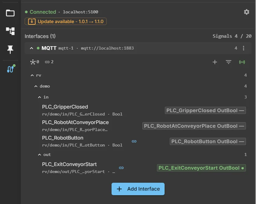
Each row shows the interface signal with its address and, on the right, the chip of the model-side signal with the same name. A link icon marks a row the model actually binds; a green dot on the chip means a live value has arrived. The panel header counts admitted signals against the license limit — Signals 4 / 20 on the free tier.
6. Check that data flows
Section titled “6. Check that data flows”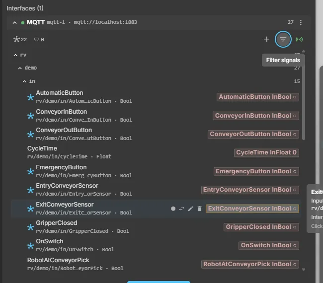
In the CONNECT panel:
- The interface card shows Connected and a signal count.
- Values move when the machine moves.
- Writing a command signal from the HMI reaches the controller only when
Allow web to PLCis enabled on that interface. It is off by default — see configuring interfaces.
See also
Section titled “See also”- Connecting a PLC — the same set-up for virtual commissioning, with write access to the PLC
- Configuring interfaces — signals, directions, write access
- Supported protocols — connection parameters per protocol
- Troubleshooting — connected but no values, or values but no movement