
Components Overview
A component gives a model node a function. A Drive moves the node. A Sensor detects parts. A Lamp lights up when a signal is set. A model is a tree of CAD parts with components attached.
The GLB file stores the components with the model. Every viewer that opens the file runs them the same way.
Adding a component
Section titled “Adding a component”There are two ways, both in the Editor:
- Quick Edit on the right has buttons for the components you need most often — see the Quick Edit Reference.
- ADD COMPONENT at the bottom of the property inspector lists every component that can be added to the selected node. Double-click a node in the hierarchy to open its inspector.
Select the node first. A component acts on its node and everything below it. Put a drive on the node that holds all moving parts.
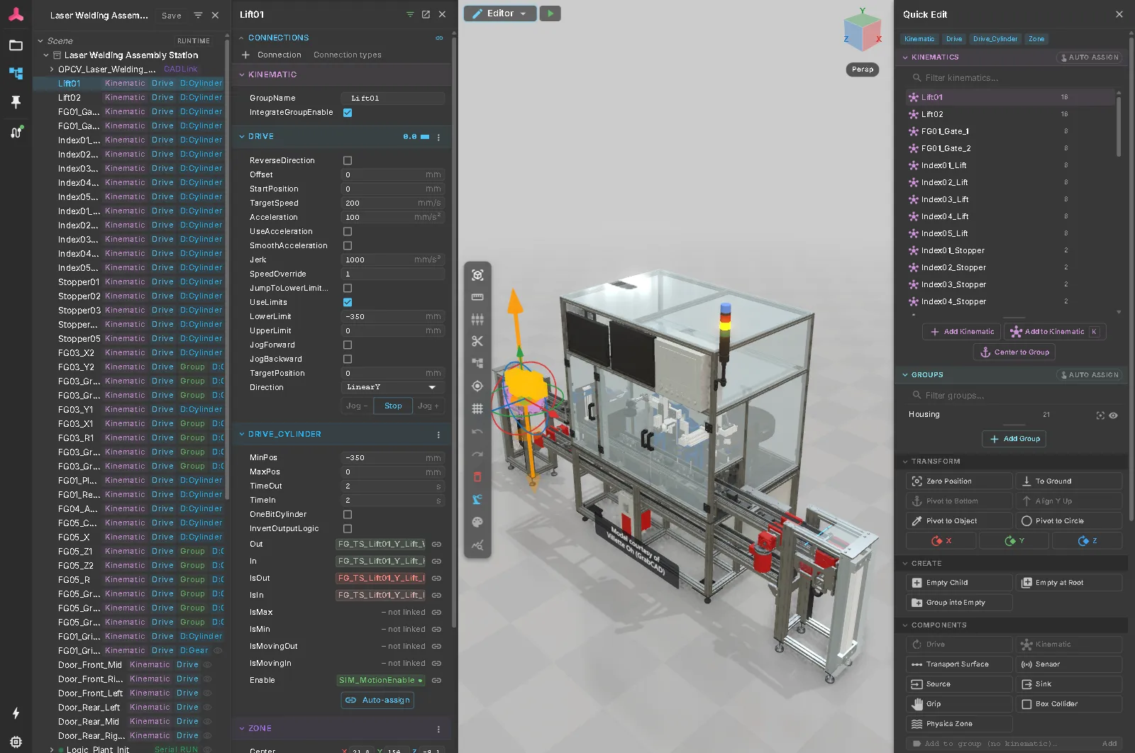
The property inspector shows the component’s settings. Enter values in the unit shown (mm, mm/s, °).
Click Link signal to connect a signal field; see Signal Binding. Reference fields list matching parts, such as the sensors a logic step can wait for.
All components
Section titled “All components”| Component | What it does | Page |
|---|---|---|
| Drive | Moves a node along or around an axis | Drives |
| Drive behaviours | Control a drive the way a real actuator does: cylinder, servo, conveyor motor, device profiles | Drives |
| Pulse Encoder | Toggles a signal every few millimetres of drive travel | Drives |
| Energy Chain | Turns a rigid CAD cable carrier into a moving chain | Drives |
| Transport Surface | A conveyor that carries parts | Material Flow |
| Source / MU | Creates parts | Material Flow |
| Sink | Removes parts | Material Flow |
| Sensor | Detects parts | Material Flow |
| Transport Stopper | Stops parts on a conveyor | Material Flow |
| Zone | A box that detects, stops or carries parts | Material Flow |
| Grip / Grip Target | Picks and places parts | Gripping |
| PLC signals | Values exchanged with a controller | Signals and Logic |
| Logic steps | Sequences that run the model without a controller | Signals and Logic |
| PLC Program | A Structured Text program run by the virtual PLC | Virtual PLC (ST) |
| Connection Mode | Whether the model starts on its own logic or a real PLC | Signals and Logic |
| Lamp | A part that lights up from a signal | HMI Markers |
| Web Sensor, Web Visibility, Web Error, Web Diagnostics | Show signal states, errors and diagnoses on the part they concern | HMI Markers |
| Operator Panel | A control box with buttons, lamps and E-stops | Operator Panel |
| 3D buttons | Push buttons, emergency stops and switches in the 3D scene | HMI Markers |
| Collision Role | Reports parts that touch | Collision Detection |
| Box Collider, Physics Zone | Physical parts that fall, slide and stack | Physics |
| Mechanism and its joints | Closed-loop kinematics such as a delta robot | Rigid-Body Mechanisms |
| Chain | Chain conveyors and bucket elevators | Chain Conveyors |
| Ribbon components | Paper, film or foil running over rollers | Ribbon Handling |
| Machining Volume / Machining Tool | Material removal by a cutting tool | CSG Machining |
| FMU | An FMI co-simulation model inside the twin | Attach and Run an FMU |
See also
Section titled “See also”- Quick Edit Reference — the buttons that add the common components
- Your First Twin from CAD — a drive on a real CAD file, step by step
- Demo Models — models that use most of these components
- rv-ODT specification — the exact file format of every component