
Signals and Logic
PLC signals control a twin through the same inputs and outputs as a real controller. Choose how to set them:
- a real PLC, connected through realvirtual CONNECT, or
- logic steps in the model itself — a virtual PLC that runs the twin without a controller, or
- a Structured Text program in the browser — see Virtual PLC (ST).
PLC signals
Section titled “PLC signals”A signal is a node with one of six signal components: PLC Input or PLC Output, each as Bool, Int or Float.
| Signal | Direction |
|---|---|
| PLCInput… | The twin writes it, the PLC reads it — a sensor state, a position feedback |
| PLCOutput… | The PLC writes it, the twin reads it — a motor command, a lamp |
Create signals with the Signals buttons in Quick Edit, and give them the name of the PLC tag. Comment appears in tooltips to help you match tags to slots.
See Signals & Alarms for signal display and colours. See Signal Binding to link a signal to a drive, sensor or lamp.
Logic steps
Section titled “Logic steps”Logic steps are a sequence of simple actions — move a drive, wait for a sensor, set a signal, wait. They run the twin when no controller is connected: for a demo, a test of the mechanics, or as a virtual PLC for commissioning.
A container holds a sequence. Steps run in the order of the hierarchy.
| Step | What it does |
|---|---|
| Serial Container | Runs its steps one after another. A top-level container starts again when it reaches its end |
| Parallel Container | Runs its steps at the same time and ends when all have ended |
| Drive To / Start Drive | Moves a drive to a Destination (mm or °), Relative to its current position if set. Drive To waits for the arrival, Start Drive does not |
| Set Signal | Sets a Bool signal to true or false |
| Wait Sensor | Waits until a sensor is occupied — or free. WaitForStopped also waits until the part has come to a halt |
| Wait Zone | Waits until a zone is occupied or free |
| Wait Signal | Waits for a signal value, or for a rising or falling Edge |
| Wait Drives | Waits until several drives have reached their targets |
| Jump | Jumps to a named step of the same container when a Bool signal has the value set in JumpOn — for loops and branches |
| Delay | Waits a number of seconds |
| Pause | Currently has no effect in realvirtual |
Models exported from Unity can carry further step types, for example Set Drive Speed, Set Signal Float, Wait Signal Float, Enable and the Grip Pick / Grip Place steps. They run in realvirtual too, but you cannot add them in the Editor.
To build a sequence in the Editor:
- Select an empty node and click LogicSteps Container in Quick Edit.
- Keep the container selected and click a step to add it inside the container. The new step is then selected; clicking the next step inserts it right after.
- Double-click the step to choose its drive, sensor or signal in the property inspector.
See the Quick Edit Reference for details.
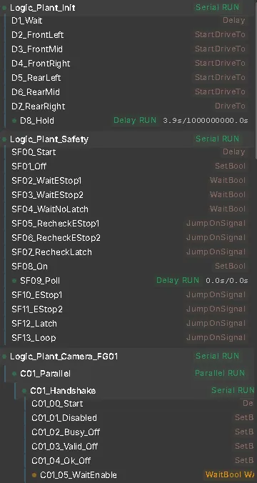
While the twin runs, the hierarchy shows each sequence with its state, for example Serial RUN.
Simulation or PLC
Section titled “Simulation or PLC”A model with logic steps can run on that logic or on a real controller. The Connection Mode component on a node of the model sets how it starts: Simulation (the logic steps run) or PLC (a real controller is expected).
While an interface is connected, a SIM / PLC button next to the simulation controls changes the mode. A connected controller takes over automatically when it writes its first output.
Use each step’s Active setting to limit it to one mode. This lets plant behaviour, such as doors or an E-stop chain, keep running while the virtual PLC stops. Simulation or PLC describes the switch.
A Structured Text program follows the mode only if it reads the system variable RV_SimulationMode — see Simulation or PLC mode. If it writes the same outputs as logic steps, resolve that in the model yourself.
See also
Section titled “See also”- Virtual Commissioning — all commissioning functions at a glance
- Signals & Alarms — how signals are shown, and the Simulation / PLC switch
- Signal Binding — connecting signals to component slots
- Virtual PLC (ST) — control logic in Structured Text instead of logic steps
- Operator Panel — buttons and lamps on the signals
- Laser Welding Assembly Station — a complete virtual PLC on 193 TIA tags