
Drives
A Drive moves its node and everything below it along or around one axis. It is the basis of every movement in a twin: a conveyor belt, a lifting table, a robot joint, a door.
A drive on its own moves at its target speed when commanded. A drive behaviour on the same node reads PLC signals to control when and how it moves, as a real cylinder, servo or conveyor motor would.
Adding a drive
Section titled “Adding a drive”- In the Editor, select the node that holds all moving parts — usually an axis node, see Kinematics.
- Put the pivot where the part turns or slides from, for example with Pivot to Circle.
- Click Drive in Quick Edit. The drive starts as LinearX.
- Double-click the node in the hierarchy and set Direction in the property inspector.
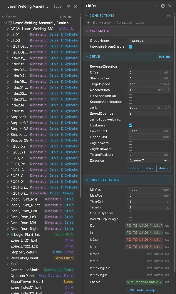
- Use Drive Test in Quick Edit to jog the drive while editing. During a test run, use Jog − and Jog + in the inspector.
Your First Twin from CAD shows these steps on a robot arm.
Settings
Section titled “Settings”| Setting | What it does |
|---|---|
| Direction | The axis: LinearX/Y/Z to slide, RotationX/Y/Z to turn, Virtual for a drive that only computes a position and moves nothing |
| ReverseDirection | Swaps the positive direction |
| TargetSpeed | Speed in mm/s, or °/s for a rotary drive |
| UseAcceleration / Acceleration | Ramps the speed up and down instead of jumping to it (mm/s² or °/s²) |
| SmoothAcceleration / Jerk | Rounds off the ramps (S-curve). Needs UseAcceleration |
| UseLimits / LowerLimit / UpperLimit | Restricts the travel. Units are mm or ° |
| JumpToLowerLimitOnUpperLimit | Wraps around at the limits instead of stopping — for a turntable that turns endlessly |
| StartPosition / Offset | Where the drive starts, and the shift of its zero point |
| SpeedOverride | A factor on the speed of this one drive, multiplied with the global speed |
The property inspector shows the units of a rotary drive in degrees automatically. Settings ▸ Visual ▸ Display ▸ Drive axis gizmo draws the axis, the travel range and the current position of the selected drive into the model.
Drive behaviours
Section titled “Drive behaviours”Add a behaviour to a node that already has a Drive. A drive takes one behaviour that moves it; Position Switch only reads the position and can be added to any drive.
| Behaviour | Typical use | Main signals |
|---|---|---|
| Simple | A motor with forward and backward commands — a conveyor, a jog axis | Forward, Backward, Speed |
| Cylinder | A pneumatic cylinder with two end positions, travel times and end-position feedback | Out, In, IsOut, IsIn |
| Destination Motor | A servo axis that moves to a destination on a start signal | StartDrive, Destination, IsAtDestination |
| Continous Destination | Like Destination Motor, but a new destination starts the move without a start bit | SignalDestination, SignalIsAtDestination |
| Speed | A motor whose speed comes from a signal | SignalTargetSpeed |
| Follow Position | An axis that follows a position signal directly, such as an FMU output | Position |
| Gear | Follows a master drive with a ratio — set MasterDrive and GearFactor | — |
| Position Switch | Switches a signal while the axis is inside given position ranges | OutputSignal |
| Erratic Position | Moves randomly between two positions, for demos and tests | — |
| SEWMovilink, Profidrive Speed, Profidrive Pos, Festo FHPP, Uni Drive Motor, Proportional Valve | The drive profiles of real devices, with their control and status words | Device-specific |
A behaviour’s signal slots appear in the property inspector. Click Link signal for each slot, or drag a signal onto it. See Signal Binding. Destination Motor creates its standard signals automatically if you leave the slots empty.
Signals control a drive with a behaviour, so Drive Test cannot jog it. Use the signals or a test run.
Pulse Encoder
Section titled “Pulse Encoder”A Pulse Encoder on a drive node toggles a Boolean PLC input every time the drive has travelled another PulseIntervall (mm or °). It imitates an incremental encoder for a controller that counts pulses. Offset sets the position of the first pulse; 0 as interval switches it off.
Energy Chain
Section titled “Energy Chain”An Energy Chain turns a rigid CAD cable carrier into a chain that moves with the axis. It has a straight run and a bend that travels at half the speed of the moving end. Its length stays constant.
Add it to the cable carrier node. Leave bend radius, link height and length at 0 to measure them from the CAD shape. If the bend is upside down, switch BendUp.
See also
Section titled “See also”- Quick Edit Reference — Kinematics, Drive Test and testing
- Signals and Logic — moving drives from a sequence without a controller
- Rigid-Body Mechanisms — several drives in a closed loop, with force analysis for drive sizing
- Material Flow — drives that move conveyors