
Supported Protocols
CONNECT speaks one protocol per interface, and several interfaces can run side by side in one gateway. This page lists what each one needs and what is worth knowing before the first connection attempt.
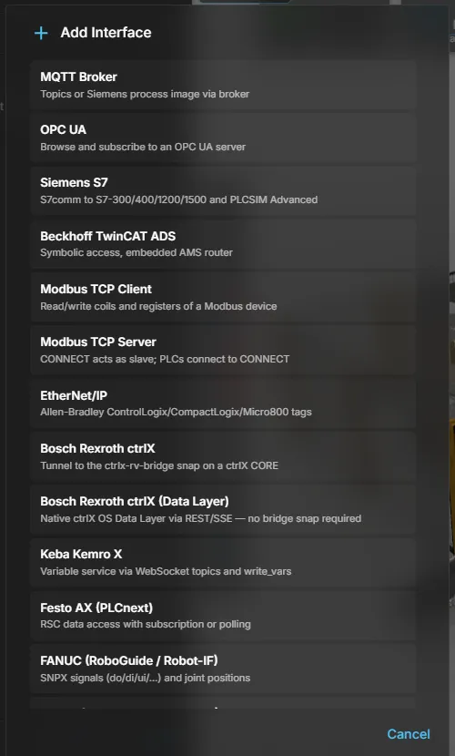
All supported interfaces
Section titled “All supported interfaces”Twenty-seven interface types ship in the current build — the same list the Add Interface dialog offers. FMU co-simulation is offered there too and has its own page: FMU.
| Interface type | Target system | Address | Signals found by |
|---|---|---|---|
| MQTT Broker | Any MQTT broker; Siemens process image; flat JSON (SEW MOVI-C) | Topic | Browse, tag-table or symbol-table import |
| OPC UA | Any OPC UA server | NodeId | Browse |
| Siemens S7 | S7-300/400/1200/1500, PLCSIM Advanced over S7comm | DB1.DBX0.0 | Manual, or browse a TIA .sdf symbol table |
| Siemens PLCSIM Advanced (native API) | PLCSIM Advanced on this machine or on another PC, through the Siemens simulation API | Tag name | Browse |
| Beckhoff TwinCAT ADS | TwinCAT 2 and 3, CX, soft-PLC | Symbol | Browse |
| Modbus TCP Client | Drives, sensors, Modbus gateways | HR40001 | Manual |
| Modbus TCP Server | A PLC or SCADA connecting to CONNECT | HR0 | Manual |
| EtherNet/IP | Allen-Bradley ControlLogix, CompactLogix, Micro800, Omron | Tag | Browse |
| B&R PVI (ANSL/INA2000) | B&R controllers and ArSim, through the B&R PVI installation on this PC | gCounter, Prog1:localCnt, stData.Speed | Browse |
| Mitsubishi MELSEC (MC 3E) | MELSEC iQ-R, Q, L and iQ-F over MC protocol (SLMP 3E binary) | D100, M0, D200:float | Manual, or browse a GX Works3 CSV export |
| UDP (binary telegram) | A PLC, SCADA system or your own tool exchanging fixed binary telegrams | 0:BOOL, 4:INT, 8:REAL | Manual, or browse a CSV symbol table |
| Bosch Rexroth ctrlX | ctrlX CORE through the bridge snap | Node path | Browse |
| Bosch Rexroth ctrlX (Data Layer) | ctrlX CORE natively, no snap needed | Node path | Browse |
| Keba Kemro X | Keba controllers | Variable | Browse |
| WebSocket Realtime (realvirtual v2) | realvirtual for Unity, another CONNECT or the ctrlX bridge — CONNECT as server or client | Signal name | Browse (the signals the peer offers) |
| Festo AX (PLCnext) | Festo AX, Phoenix Contact PLCnext | Variable | Browse |
| FANUC (RoboGuide / Robot-IF) | FANUC controller or RoboGuide | do4, di1 | Manual |
| Denso (b-CAP / WinCaps VRC) | Denso RC8/RC9, WinCaps VRC | IO104, P10, axis1 | Manual |
| KUKA OfficeLite (Y200 TCP) | KUKA OfficeLite through the OC_Assistant_OfficeLite Y200 server | in1, out1, axis1 | Manual |
| KUKA iiQKA / RSI (UDP) | KUKA iiQKA VRC or a KUKA controller with RSI Ethernet | digin1, digout1, axis1 | Manual |
| Universal Robots (RTDE) | URSim or a UR controller | do0, di0, axis1 | Manual |
| igus ReBeL (CRI) | igus robot control (iRC) and its simulation | axis1, dout20, cmd:movejoint | Manual |
| RoboDK (API) | A running RoboDK station | axis1, param:PartCount, prog:run | Manual |
| Wandelbots NOVA | A Wandelbots NOVA cell | axis1, io:<name>, prog:run | Browse (controller IOs) |
| ABB RobotStudio (SIMIT SHM) | RobotStudio on the same PC | Signal name | Manual |
| Shared Memory (SIMIT) | SIMIT or a Unity consumer on the same PC | Signal name | Manual |
| WINMOD Y200 (Shared Memory) | WINMOD on the same PC | MB13.6, MI100, MF106 | Manual, or browse a WINMOD signal list |
Browse means the controller can be asked what it offers, so signals are selected rather than typed. For S7, Mitsubishi, UDP and WINMOD the browse reads a symbol file named in the interface settings instead of asking the controller. Manual means the protocol has no browse mechanism and addresses are entered — validated against the same parser the interface uses at connect time.
Windows only: Festo AX, FANUC, Denso, ABB RobotStudio, Shared Memory (SIMIT), WINMOD Y200, B&R PVI and the native PLCSIM Advanced interface. The Linux build — for example CONNECT on a ctrlX CORE — does not offer them.
Supported value types are Boolean, integer and floating point throughout, plus text where the protocol carries it. The per-protocol sections below name the exact data types each one accepts.
OPC UA
Section titled “OPC UA”| Parameter | Example |
|---|---|
| Endpoint | opc.tcp://192.168.1.20:4840 |
Addresses are node ids as the server publishes them, for example ns=2;s=Motor1.Speed. The address space can be browsed, so signals are usually selected rather than typed.
Siemens S7
Section titled “Siemens S7”| Parameter | Example |
|---|---|
| IP address | 192.168.1.50 |
| Rack / Slot | 0 / 1 |
| Connection timeout | 10000 ms (default) |
| Symbol table | C:\Projects\Line1\Tags.sdf (optional) |
Addresses are absolute, DB-style: DB1.DBX0.0 for a bit, DB1.DBW2 for a word, DB1.DBD4 for a real. Values are read big-endian, once per update cycle.
With a symbol table set — a TIA Portal .sdf export on the gateway PC — Browse lists its symbols with address, type and a direction derived from the area (I/E is written by the viewer; Q/A, M and data blocks are read), so signals can be selected instead of typed. Without it, signals are entered manually.
On the PLC side the CPU must allow PUT/GET communication access — the same setting any third-party S7 client needs — and the addressed data blocks must have optimized block access disabled, because S7 communication cannot address optimized blocks by absolute offset.
PLCSIM Advanced
Section titled “PLCSIM Advanced”There are two ways to reach a Siemens PLCSIM Advanced instance from CONNECT. Neither of them needs a coupler process or a shared-memory bridge.
Native API — recommended
Section titled “Native API — recommended”Interface type Siemens PLCSIM Advanced (native API). CONNECT drives the official Siemens simulation API in its own process and attaches to a registered instance by name.
| Parameter | Example |
|---|---|
| Instance name | PLCSimInstance |
| Update cycle | 10 ms |
| Remote address | 192.168.1.80:50000 (optional) |
Signals are addressed by their symbolic tag name (Motor1_Start, "Data_block_1".Speed), and Browse lists the instance’s tags with their direction already derived from the memory area — %I is written by the viewer, %Q, %M and data blocks are read from it. Optional filters narrow a browse to HMI-visible tags, to named data blocks, or by regular expression.
This route has none of the restrictions of the S7comm route below: no absolute addresses, no PUT/GET, no optimized block access to disable, and Softbus works — the instance needs no virtual Ethernet adapter. CONNECT also notices a TIA software download while running and rebuilds its tag bindings instead of reading addresses that have moved.
Which tags are loaded. PLCSIM Advanced keeps its tag list to 500 000 entries, and every array and structure element counts — asking for every data block of a large (safety) project overruns it. CONNECT therefore loads the process image and the markers plus exactly the data blocks it needs: the ones named in Data Block Filter, and the ones your configured signal addresses point at (an address of the form "Data_block_1".Speed names its block; an unquoted DB1.Speed does not and stays unbound). A Browse has no signals to work from, so it lists data block tags only for the blocks you name in the filter.
If the list still overruns the limit, CONNECT retries that one browse with HMI-visible tags only and reports it as tagListFallback in GET /status and in the gateway log, next to the requested scope and filter. Your Browse HMI-visible tags only setting is never changed by this — the next connect tries the full list again. A signal whose tag was missing while the fallback was active stays unbound with a tag not found issue until you restart the interface.
Requirements. PLCSIM Advanced V4 to V7 must be installed on the machine CONNECT runs on, and the instance must already be registered and running — CONNECT attaches, it never creates or downloads an instance. CONNECT does not ship the Siemens API: it loads the one your installation provides, so your own PLCSIM Advanced license applies. This interface is Windows only and is not offered by the Linux build. If PLCSIM Advanced is not installed, the interface shows exactly that in its status and makes no connection attempt.
An instance on another PC. Set Remote address to host[:port] of that PC’s PLCSIM Advanced Runtime Manager (IPv4 address or host name, default port 50000); empty means the instance runs on the CONNECT machine. The remote PC must allow remote connections in its PLCSIM Advanced Control Panel, and PLCSIM Advanced must still be installed on the CONNECT machine, because the API is loaded from there. A malformed address is shown as a configuration error and not retried.
Not supported in this version. SyncPoint lock-step co-simulation and 64-bit integer tags (LInt, LWord) — those are reported as a signal issue rather than truncated silently.
Over S7comm
Section titled “Over S7comm”Interface type Siemens S7, pointed at the instance. Use this when PLCSIM Advanced is not installed on the CONNECT host, or when CONNECT runs on Linux.
In the PLCSIM Advanced instance settings, switch the network adapter from Softbus to PLCSIM Virtual Eth. Adapter, then enable PUT/GET in the simulated CPU’s protection settings. After that the instance is addressed exactly like a real S7-1500 — same IP, rack and slot. Softbus is not supported: only the virtual Ethernet adapter speaks TCP/IP, addresses must be absolute, and the addressed data blocks must have optimized block access disabled.
| Parameter | Example |
|---|---|
| Broker URL | mqtt://192.168.1.30:1883 |
An MQTT interface handles each topic in one of three modes, and one interface may mix them.
Single mode
Section titled “Single mode”The topic payload is one scalar value for one signal — the simplest form and the one manual signal creation produces. Values written by the viewer are published back to the topic.
Process image mode
Section titled “Process image mode”The topic payload is a raw byte array, typically a Siemens process image. A tag table unpacks it into many named signals:
- Addresses use the Siemens notation
%I3.1(bit),%IW13(word),%IB,%ID,%M,%Q. The offset is a byte offset into the payload. - Types are decoded big-endian: Bool, Byte, Word, Int, DWord, DInt, Real.
- Only the bytes that actually changed are turned into signal updates; the first message after every reconnect resends everything.
Tag tables are imported in the browser from a Siemens tag export and pushed to the gateway.
Json mode (SEW MOVI-C)
Section titled “Json mode (SEW MOVI-C)”The topic payload is one flat JSON object holding the whole process image of that topic — {"ControlWord1": 6, "SpeedSetpoint": 2048, "DriveEnable": true}. There are no addresses: the signal name is the JSON key. This is the format a SEW MOVI-C station publishes through the Codesys MQTT libraries, and the same format the SEW interface in realvirtual for Unity uses, so an existing SEW simulation can be moved to the browser unchanged.
A station uses two topics, one per direction:
| Topic | Signals | Behaviour |
|---|---|---|
Receive topic, e.g. SEW/SimOUT | PLC outputs | The station publishes; the gateway decodes and updates the signals. |
Publish topic, e.g. SEW/SimIN | PLC inputs | The gateway publishes the complete object cyclically (default every 100 ms, adjustable per topic). |
The quickest way to set this up is the catalog row SEW MOVI-C (MQTT Json) in Add Interface. It is a signal interface, the browser counterpart of the SEW SimInterface in realvirtual for Unity: it exchanges the process image of a SEW MOVI-C controller (inputs, outputs, positions, any signal the controller publishes) over MQTT. It is not tied to a drive type and has nothing to do with the MOVILINK drive behavior. The row creates an MQTT interface with both topics already configured (SEW/SimOUT receiving, SEW/SimIN publishing every 100 ms as WString) and no signals yet; import the controller’s symbol table on that interface to fill them. Under the hood it is the same MQTT interface as the plain MQTT Broker row, so everything described here applies to both.
Two settings are specific to this mode:
- Encoding —
Utf8,WString(CodesysWSTRING, that is UTF-16LE without a byte order mark) orAuto.Autois the default and detects the encoding per message; set it explicitly when the station’s format is known. - Publish interval — cycle time of the outbound object in milliseconds, limited to 20…60000 ms.
Direction matters here: only signals marked as PLC outputs are read from an incoming message, so the gateway’s own cyclic publish can never overwrite a command the viewer just issued. Writing back also needs Allow Web → PLC writes on the interface. Signal lists are imported in the browser from a SEW symbol table (Name;Type;Direction), which creates both topics with the right directions and encodings in one step.
Per topic the gateway reports how many messages arrived, how many were rejected, how many publish cycles were skipped and which encoding was detected — visible in the interface status.
TwinCAT ADS
Section titled “TwinCAT ADS”| Parameter | Example |
|---|---|
| AMS Net Id | 5.78.123.1.1.1 |
| ADS port | 851 |
| Mode | SumCommand (default), OnChange, Cyclic |
Signals are addressed by ADS symbol name (MAIN.bStart) and typed by a Beckhoff primitive: BOOL, BYTE, WORD, DWORD, SINT, USINT, INT, UINT, DINT, UDINT, REAL, LREAL.
TwinCAT does not have to be installed on the gateway PC — CONNECT starts an embedded ADS router when none is present, and steps aside when a real TwinCAT installation already owns the port.
An AMS route is still required on the PLC. This is an ADS protocol requirement: in the target PLC’s route configuration, add a route back to the gateway PC’s IP address and the configured Net Id.
Discovery reads the PLC’s symbol table and derives the direction from the I/O image — symbols on the physical input image become PLCInput (realvirtual supplies them), symbols on the output image become PLCOutput. That is the correct orientation for virtual commissioning.
Modbus TCP client
Section titled “Modbus TCP client”| Parameter | Example |
|---|---|
| Host / Port | 192.168.1.60 / 502 |
| Unit id | 1 |
| Word order | ABCD, CDAB, BADC, DCBA |
| Connection timeout | 10000 ms (default) — bounds the connect and every read and write |
Addresses name one of the four standard tables plus an offset, with an optional bit suffix:
| Prefix | Table | Writable |
|---|---|---|
HR | Holding register | yes |
IR | Input register | no |
C | Coil | yes |
DI | Discrete input | no |
Both notations are accepted: classic five-digit Modicon (HR40001 = offset 0, C00013 = offset 12) and the modern short form (HR0, C12). HR40010.3 addresses bit 3 of a holding register.
Modbus RTU is reserved in the configuration but not yet implemented.
Modbus TCP server
Section titled “Modbus TCP server”CONNECT listens as a Modbus slave and an external PLC, HMI or SCADA system connects to it as the master. The address model is the same as the client. Note that the direction meaning mirrors: what a client may only read, a server must be able to write.
EtherNet/IP
Section titled “EtherNet/IP”| Parameter | Example |
|---|---|
| Gateway | 10.10.10.10 |
| Path | 1,0 (backplane, slot 0) — leave empty for Micro800 |
| PLC type | ControlLogix, PLC-5, SLC 500, Logix PCCC, Micro800, MicroLogix, Omron |
| Timeout | 5000 ms (default) — applies to every tag |
Addresses are tag names exactly as they appear in RSLogix or Studio 5000 — MAIN.bStart for a controller-scope tag, Program:MainProgram.MyTag for a program-scope tag. The supported scalar types are BOOL, SINT, INT, DINT and REAL; arrays and UDTs are out of scope.
Discovery reads the controller’s built-in tag list.
B&R PVI
Section titled “B&R PVI”| Parameter | Example |
|---|---|
| Connection | ANSL (default) or INA2000 |
| Host / Port | 192.168.0.10 / empty = PVI default (ANSL 11169) |
| Timeout | 1500 ms (ANSL) |
| User / Password | optional ANSL login (Automation Runtime A4.61 and newer) |
| Refresh | 100 ms per variable |
| CPU poll | 2 s |
| Source / destination station | 1 / 2 (INA2000 only) |
Couples B&R controllers — Automation Runtime on a real CPU or ArSim — through B&R’s own PVI. Variables are read and written by name, so nothing has to be released in the PLC project, unlike OPC UA. Use ANSL for Automation Runtime 4.08 and newer and for ArSim; INA2000 is available for older CPUs but has not yet been verified against real hardware.
Addresses take four forms, each followed by structure members and array elements as needed:
| Address | Meaning |
|---|---|
gCounter | global variable |
Prog1:localCnt | task-local variable of task Prog1 |
Mod1::gSpeed | global variable of an application module |
Mod1::Prog1:cnt | task-local variable inside an application module |
stData.Speed, arr[3], Prog1:st.arr[2].x | a structure member or array element |
Every signal is a single value: structures and arrays are never one signal, address the member or element you need. BOOL becomes a Boolean, the integer types an integer (a value beyond 32 bits shows as a signal issue instead of being wrapped), REAL and LREAL a float, STRING and WSTRING text, TIME an integer in milliseconds. Date and time values are read as text.
Browse lists the tasks and variables with their types and expands structures and arrays into single signals — up to Max browse variables (default 5000) and 1000 elements per array. Discovered signals arrive as PLC outputs (read); switch a signal to PLCInput to write it. Each interface also publishes the CPU state as <interface>.cpu.state (0 Run, 1 Service, 2 Stop, 256 offline) and <interface>.cpu.running; the PVI licence state is shown in the interface status.
Writing needs Allow web to PLC. CONNECT writes exactly the addressed member or element — never a whole structure — and only when the viewer changes a value. Nothing is written when the interface connects or reconnects, so the PLC keeps its own values; a change made while write access is off is discarded and not sent later.
Mitsubishi MELSEC
Section titled “Mitsubishi MELSEC”| Parameter | Example |
|---|---|
| Host / Port | 192.168.3.39 / 5001 |
| Connection timeout | 5000 ms (default) |
| CSV file | C:\Projects\Line1\DeviceComments.csv (optional) |
CONNECT talks MC protocol (SLMP) 3E binary over TCP — set up a matching open port in the PLC’s Ethernet configuration. Addresses are a device plus a number with an optional value type: M0, X1F, Y10, D100, D200:float, D300:int32, W1A0, T5. Supported devices are X Y M S SM D W R SD T C; X, Y and W are numbered hexadecimal, as in GX Works3, the others decimal. Word devices are 16-bit integers by default; :int32 and :float use two consecutive words, low word first. T and C read the current value.
The direction comes from the signal type: a PLCInput is written to the PLC, a PLCOutput is read. SM and SD are never written. Reads are combined into as few batch requests as the protocol limits allow, and writes send only changed values — registers between two written signals are never touched.
An error code returned by the PLC — for example a device outside the configured range — appears as a signal issue while the connection stays up. With a CSV file set, Browse lists the devices of a GX Works3 device-comment export, with filters per device type.
| Parameter | Example |
|---|---|
| Local port | 11001 (listens on all network adapters by default) |
| Remote host / port | 127.0.0.1 / 11000 |
| Byte order | little-endian (default) or big-endian |
| Symbol table | C:\Projects\Line1\udp-symbols.csv (optional) |
UDP exchanges one fixed binary telegram per direction. Each signal names its byte offset and type: 0:BOOL (1 byte), 4:INT (32-bit integer) or 8:REAL (32-bit float). The direction comes from the signal type — PLCInput signals form the telegram CONNECT sends every update cycle, PLCOutput signals are read from the telegram it receives. The telegram length is the end of the last field.
A received datagram that is shorter than the configured fields keeps the uncovered values and reports a signal issue instead of being dropped. UDP has no connection: the interface shows Connected once its port is bound, whether or not the partner is sending. With a symbol table (Name;Type;Direction, separator configurable) Browse lists its signals with the offsets already computed.
Bosch Rexroth ctrlX
Section titled “Bosch Rexroth ctrlX”There are two ways to reach a ctrlX CORE, and they are chosen by interface type.
Data Layer (native)
Section titled “Data Layer (native)”CONNECT authenticates against the ctrlX identity manager and uses the Data Layer API directly. Nothing has to be installed on the device.
| Parameter | Example |
|---|---|
| Address / Port | 192.168.1.30 / 443 |
| User / Password | device credentials |
Addresses are Data Layer node paths, for example plc/app/Application/sym/MAIN.fSpeed. TLS validation is on by default; accept an untrusted certificate only for a device you deliberately trust with its factory certificate.
Bridge tunnel
Section titled “Bridge tunnel”The alternative routes through the ctrlx-rv-bridge snap running on the device. This requires a double deployment: the snap on the ctrlX CORE plus the interface here. Without the snap the interface reports exactly that. An optional bridge publish interval (ms) is sent to the bridge on connect; left empty, the bridge keeps its own setting.
Both modes use the same node paths, so an interface can be moved from one to the other.
| Parameter | Example |
|---|---|
| Host | 192.168.1.100 |
| User / Password | controller credentials |
| Output / input topic | realvirtual_outputs / realvirtual_inputs |
| Connection timeout | 10 s (default) |
Addresses are fully qualified Keba variable names (PLC.app.Speed). Values arrive as pushes over the variable service; writes go out by variable name. Discovery browses the variable tree from configurable root paths and can infer the direction from name patterns. The input topic collects the variables realvirtual writes, as in realvirtual for Unity; leave it empty to create none. A login that does not answer within the connection timeout shows as an error and is retried with the normal reconnect delay.
WebSocket Realtime
Section titled “WebSocket Realtime”| Parameter | Example |
|---|---|
| Mode | Server (default) or client |
| Server: bind address / port | 127.0.0.1 / 8080 |
| Client: address / port / path | 192.168.1.40 / 8080 / empty |
| API key | required before the server accepts other machines |
The realvirtual WebSocket protocol v2 — the one the WebSocket Realtime interface of realvirtual for Unity and the ctrlX bridge speak. As server, CONNECT listens on its own port, separate from the gateway port; as client, it connects to a Unity scene or another server and subscribes to its signals. Signals are addressed by the name used on the wire, which may differ from the local signal name. Browse asks the connected peer for its signal list and turns the peer’s inputs into outputs here and vice versa; name patterns can preset the direction.
Festo AX / PLCnext
Section titled “Festo AX / PLCnext”| Parameter | Example |
|---|---|
| Host / Port | 192.168.1.10 / 41100 |
| User / Password | controller credentials |
| Connection timeout | 10 s (default) |
| Validate certificate | on (default) |
Addresses are GDS variable paths, for example Arp.Plc.Eclr/MainInstance.bStart. Subscription is used when the controller accepts it, with polling as the fallback. Validate certificate only matters for an encrypted connection; switch it off only for a test PLCnext with a self-signed certificate.
| Parameter | Example |
|---|---|
| Address / Port | 127.0.0.1 / 60008 |
| Axis count | 6 |
Addresses are FANUC signal names — a prefix plus a number, such as do4, di1, ui1, ao2. The prefix decides the direction: robot outputs (do, uo, ro, sdo, ao, wo) are read by realvirtual, robot inputs (di, ui, ri, sdi, ai, wi) are written by it.
With an axis count set, the robot’s joint positions are published additionally as <interface>.axis1 … axisN.
A RoboGuide cell with several robots uses one port per robot, incrementing from 60008.
| Parameter | Example |
|---|---|
| Host | 127.0.0.1 |
| Controller type | RC8 or RC9 |
| WinCaps project | C:\Projects\Cell1\Cell1.WPJ |
Addresses are VRC variable symbols: IO<n> for a Boolean, I<n> integer, F<n> float, S<n> string. Joint positions are published as <interface>.axis1 … axisN; an address axis<n> binds a joint under a signal name of your own instead. A virtual controller connection needs the WinCaps project file on the gateway PC.
A position variable P<n> becomes six signals <name>.x, .y, .z (mm) and .rx, .ry, .rz (degrees) plus <name> holding the robot figure, where <name> is the signal’s name. As a PLCOutput it is read; as a PLCInput it is written as one position with the figure the controller reported — and, like every write, only with write access.
KUKA OfficeLite
Section titled “KUKA OfficeLite”| Parameter | Example |
|---|---|
| Host / Port | 127.0.0.1 / 54600 |
| Max digital signals | 10 (up to 8192) |
| Axis count | 6 |
Couples to KUKA OfficeLite through the OC_Assistant_OfficeLite Y200 server. Addresses follow KUKA’s numbering: in1 is $IN[1] (written by realvirtual), out1 is $OUT[1] (read), axis1 … axis6 are the joints in degrees. Joint positions are also published as <interface>.axis1 … axisN. Bits above Max digital signals are not exchanged and show as a signal issue.
Not to be confused with WINMOD Y200, which is a shared memory on the same PC.
KUKA iiQKA / RSI
Section titled “KUKA iiQKA / RSI”| Parameter | Example |
|---|---|
| Listen address / RSI port | 0.0.0.0 / 49152 |
| Cycle | 4 ms (4, 8 or 12) |
| Axis count | 6 (up to 12) |
| Digital / analog channels | 8 / 0 |
CONNECT is the UDP server of an RSI Ethernet context: the KUKA iiQKA VRC or controller sends a packet every cycle and CONNECT answers each one at once, echoing its IPOC. Until the first packet arrives the interface shows Connecting; when packets stop for ten receive timeouts in a row it reconnects. Addresses: digin<n> and anain<n> are written by realvirtual, digout<n> and anaout<n> are read, axis<n> are the joints (actual or set-point positions, selectable). Joint positions are also published as <interface>.axis1 … axisN.
Universal Robots
Section titled “Universal Robots”| Parameter | Example |
|---|---|
| Host | 192.168.0.4 |
| RTDE / secondary port | 30004 / 30001 |
| Output frequency | 20 Hz |
Joint positions, digital outputs and robot state are read over RTDE; joints are converted to degrees and also published as <interface>.axis1 … axis6. Addresses: do0 … do7 and cdo0 … cdo7 (digital and configurable outputs, read), di0 … di7 and cdi0 … cdi7 (inputs, written), axis1 … axis6, status and runtime. IO numbering is zero-based, as on the teach pendant. Inputs are set with a short URScript program on the secondary port, sent only when a value changes.
igus ReBeL
Section titled “igus ReBeL”| Parameter | Example |
|---|---|
| Host / Port | 127.0.0.1 / 3921 |
| Axis count | 6 (up to 9) |
| Speed (override) | 100 % |
Connects to the igus robot control (iRC) or its simulation over the CRI protocol. Addresses: axis<n> (joints in degrees, also published as <interface>.axis1 …), dout<n> (digital output bit, read), gsig<n> (global signal, written), cmd:override and cmd:active (override and enable, written).
cmd:movejoint and cmd:movecart start a move on a rising edge to the set-point signals <interface>.setpoint.axis1 … or <interface>.setpoint.x … rz (cartesian, in robot base coordinates); progress comes back as <interface>.move.busy, .done and .error. A move requested while another one runs is rejected, and a trigger that stays on across a reconnect starts exactly one move. Override and enable on connect are sent only with write access.
RoboDK
Section titled “RoboDK”| Parameter | Example |
|---|---|
| Host / Port | localhost / 20500 |
| Robot name | empty = first robot of the station |
| Program name | MainProgram (optional) |
Talks to a running RoboDK through its API — CONNECT never starts RoboDK or opens a station by itself, and your RoboDK licence must allow API access. Addresses: axis<n> (joint values in RoboDK’s units, also published as <interface>.axis1 …), param:<name> (a station parameter, read every 500 ms or written on change depending on the signal direction), sim:speed (simulation speed), and prog:run, prog:stop, prog:loop to control the named program. Program feedback comes back as <interface>.prog.busy, .done and .error. Switching RoboDK to simulation mode and setting its speed on connect happen only with write access.
Wandelbots NOVA
Section titled “Wandelbots NOVA”| Parameter | Example |
|---|---|
| Server | http://192.168.1.90 |
| Cell / motion group | cell / 1@fanuccrx10ial |
| Token, or user and password | NOVA credentials |
Joint positions arrive over the NOVA state stream (converted to degrees, also published as <interface>.axis1 …) and controller IOs over the IO stream. Addresses: axis<n>, io:<name> (Boolean, integer or float IO) and prog:run, prog:stop, prog:loop, which run the Wandelscript program template from the interface settings. A run that exceeds the program timeout (default 300 s) is stopped and reported in <interface>.prog.error. Browse lists the controller’s IOs. The token and password are not shown again after saving.
Moves and program starts on igus, RoboDK and NOVA need Allow web to PLC, react to a rising edge only and are never repeated after a reconnect.
ABB RobotStudio
Section titled “ABB RobotStudio”CONNECT publishes a SIMIT-layout shared memory that RobotStudio’s SIMIT connection attaches to. Windows shared memory means RobotStudio and the gateway must run on the same PC — the usual RobotStudio virtual commissioning setup.
Addresses are the signal names RobotStudio shows in its SIMIT signal list. Joint values named Joint* arrive in radians and are exposed in degrees.
Shared memory (SIMIT)
Section titled “Shared memory (SIMIT)”The same mechanism for any SIMIT-compatible consumer, including a Unity SharedMemoryInterface, with the full SIMIT type palette: Bool, Byte, Word, Int, DWord, DInt, Real.
Set the global namespace option when the gateway runs as a Windows service while the consumer runs in an interactive session. Signal names must be ASCII.
WINMOD Y200
Section titled “WINMOD Y200”| Parameter | Example |
|---|---|
| Shared memory name | Y200 |
| Mutex timeout | 1000 ms |
| Keep-alive | 0 s = off |
| Signal list | C:\Projects\Line1\winmod-signals.txt (optional) |
Couples to WINMOD through its Y200 shared memory. WINMOD creates the memory and CONNECT attaches to it — so WINMOD and the gateway must run on the same Windows PC, and the interface shows an error until WINMOD has started. Addresses are positions in the Y200 memory: MB13.6 (bit), MB7 (byte), MI100 (16-bit integer), MD102 (32-bit integer), MF106 (real). The direction comes from the signal type. Real outputs whose name starts with Joint are converted from radians to degrees.
With a keep-alive set, an interface whose WINMOD has stopped updating its cycle counter for that many seconds reports an error and attaches again. A WINMOD signal list can be browsed, but it carries PLC addresses (%E 0.0), not Y200 positions — complete each imported signal with its MB/MI/MD/MF address.
See also
Section titled “See also”- Configuring interfaces — signals, direction and write access
- Troubleshooting — connection and signal problems