
Operator Panel
An operator panel shows the machine’s controls next to its 3D model. It includes illuminated push buttons, two-position selector switches, emergency stops and a stack light. A status line tells the operator what to do next. The controls look and behave like those on the real machine.
The panel is stored as data in the model, without code. The viewer opens it in a separate window when the GLB loads. This works for the main model and for every placement of it in a layout.
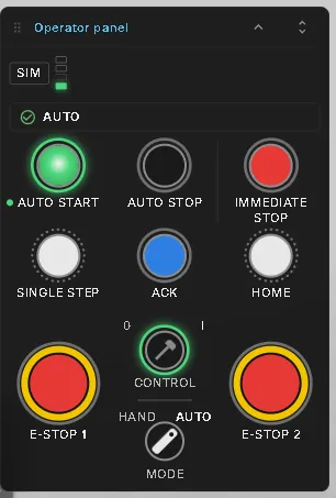
The Laser Welding Assembly Station includes a complete panel. Open it in HMI mode to try the controls on this page.
What is on the panel
Section titled “What is on the panel”| Device | How it behaves |
|---|---|
| Push button | Writes its PLC input while held and releases it when you let go. Its lamp ring shows the connected PLC output |
| Selector switch | A knob or key with two positions, such as Hand / Auto. It stays in the selected position |
| E-stop | A latching mushroom button. Press to latch it; releasing takes a short hold on the pressed button, like twisting a physical E-stop to release it. Press R to release it from the keyboard |
| Stack light | A signal tower at the top of the panel, with each segment driven by a PLC output |
| Status line | A message about the machine state, such as AUTO, STOPPED: press AUTO START or FAULT: release E-stop 1 |
| Chips | Short markers at the top of the panel. The first one always shows the control mode: SIM while the virtual PLC runs, PLC with a lock while a real controller is in charge. Further chips come from the panel, such as HAND in manual mode |
Colours follow IEC 60204-1: red for emergency and immediate stop, blue for acknowledge, green or white for start, yellow for intervention. A lamp shows the colour of the output it is wired to, so a black Auto Stop cap can carry a blue lamp.
Every button writes a PLC input and every lamp reads a PLC output. This follows the standard signal convention. The PLC determines what each button does. When no controller is connected, the model’s virtual PLC controls the response.
In virtual commissioning
Section titled “In virtual commissioning”The panel is a virtual commissioning function: its buttons and switches write the same PLC inputs as the real control panel, and its lamps show the same PLC outputs. A connected controller therefore receives the original operator signals, and its program is tested with the original operating sequence — in PLC mode by the real or simulated controller, in SIM mode by the model’s virtual PLC.
Stopping and restarting
Section titled “Stopping and restarting”The status line shows the steps to recover from a fault and counts them.
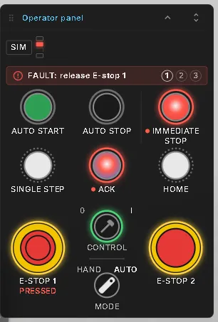
On the welding station:
- Press E-STOP 1. Every axis stops at once and the status line shows a fault.
- Hold the pressed E-stop until its ring fills and the button releases. The status line now asks for ACK.
- Press ACK to acknowledge the fault. The station waits in STOPPED.
- Press AUTO START. Every station continues from where it stopped.
Auto Stop lets the station finish its current work before stopping. Press Auto Start to resume.
Moving and collapsing the window
Section titled “Moving and collapsing the window”Drag the title bar to move the panel out of the way. The viewer remembers its position.
Click the arrow in the title bar to collapse the panel to its title bar. Click it again to open the panel; the viewer remembers whether it was open or collapsed.
Adding a panel to your own model
Section titled “Adding a panel to your own model”A panel is a WebOperatorPanel component on any node of the model. Its Config field stores the panel as JSON. This defines the devices, their grid positions, the signals they read or write, the status rules and the restart steps. Every signal name must exist in the model.
Create the configuration in one of three ways:
- In the Editor, add the component to a node and paste the configuration into its Config field. The window appears when the field is valid. Errors appear in the window and the Problems panel.
- Ask an AI assistant through the AI bridge. It lists the model’s signals, builds the configuration and checks the result. Its guide,
web_help("operator-panel"), also contains the welding station’s complete configuration. - Generate it with a build script, like any other component field.
Save the model to keep the panel with it.
See also
Section titled “See also”- Virtual Commissioning — all commissioning functions at a glance
- Signals & Alarms — the signals behind the buttons and lamps, and the Simulation / PLC switch
- Demo Models — the Laser Welding Assembly Station
- Signal Binding — connecting the model’s signals to a real controller