
HMI Markers
HMI markers show machine state on the relevant parts. Examples include lamps, sensors that change colour, flashing error markers and station labels. They do not change how the machine moves.
Most of them read a PLC signal. Link it in the property inspector with Link signal — see Signal Binding.
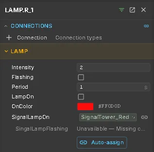
A Lamp makes its part glow in a colour when a signal is set — a signal tower segment, an illuminated push button, an indicator.
| Setting | What it does |
|---|---|
| SignalLampOn | The signal that switches the lamp on |
| SingalLampFlashing | The signal that makes the lamp flash |
| OnColor | The colour when lit. Click the swatch to choose a colour |
| Intensity | How strongly it glows |
| Flashing / Period | Flashes instead of staying on; period in seconds, half on, half off |
| LampOn | The state when no signal is linked |
The lamp lights the first mesh below its node.
Web Sensor
Section titled “Web Sensor”Shows a sensor state as a colour on the part: Low, High, Warning or Error. SignalBool gives the two states Low and High. For more states, use SignalInt with IntStateMap, for example 0=Low;1=High;2=Warning;3=Error. Label is shown in the tooltip and the sensor list.
Web Visibility
Section titled “Web Visibility”Shows or hides a part based on a signal. Use it for variant-specific parts or to hide a door and see inside.
SignalVisible controls visibility. InvertSignal reverses the signal, and DefaultVisible applies when no signal is linked. AdditionalTargets shows or hides other parts at the same time. Web Visibility can also carry an error state like a Web Error.
Web Error
Section titled “Web Error”Marks a part as faulty while a signal is set: the part flashes and a badge shows ErrorText, which also appears in the message panel. HighlightStyle chooses how the part is marked: FlashObject for the part itself, Circle for a ring around a small part, Auto decides by size. Without a signal it is a permanent hint marker.
Web Diagnostics
Section titled “Web Diagnostics”Connects a PLC error signal to the AI diagnosis. A rising SignalBool or a non-zero error code on SignalInt opens a diagnosis for the part, using the machine documentation.
DocFilter limits which documents the diagnosis searches. Label names the card. AutoOpen controls whether the dialog opens automatically or only the card appears.
Web Label
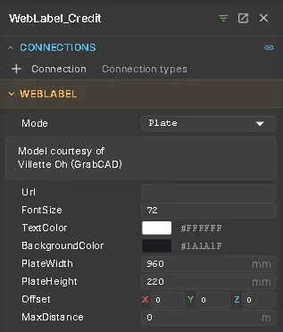
Section titled “Web Label”Adds a text label to a node, such as a station name, note or link. Billboard labels always face the camera and keep their size on screen. Plate labels are flat signs in the model; geometry can hide them.
Text supports several lines. Url makes the label a link. Use the colour pickers for text and background colours. MaxDistance (m) hides the label when the camera is further away.
Operator Panel
Section titled “Operator Panel”A control box with push buttons, selector switches, E-stops and a stack light, as a window over the 3D view. It is described on its own page: Operator Panel.
Tooltips, notes and AAS links
Section titled “Tooltips, notes and AAS links”- Runtime Metadata — the content of a part’s tooltip.
- Node notes — written knowledge about a part, shown in the property inspector. An AI assistant writes them; see notes on a node.
- AAS Link — connects a part to its Asset Administration Shell, by AASId and an optional ServerUrl.
3D buttons and switches
Section titled “3D buttons and switches”Models built in Unity can include clickable buttons in the 3D scene: Push Button 3D (momentary or latching, with a light), Emergency Button 3D (a latching mushroom head) and Handle Switch 3D (a lever). Each writes a PLC input. Use them in simulations. They never replace a hard-wired emergency stop.
See also
Section titled “See also”- Signals & Alarms — how signal states and messages are shown
- Machine Information System — what a part can tell an operator
- Operator Panel — the control box as a window
- Signals and Logic — the signals behind the markers