
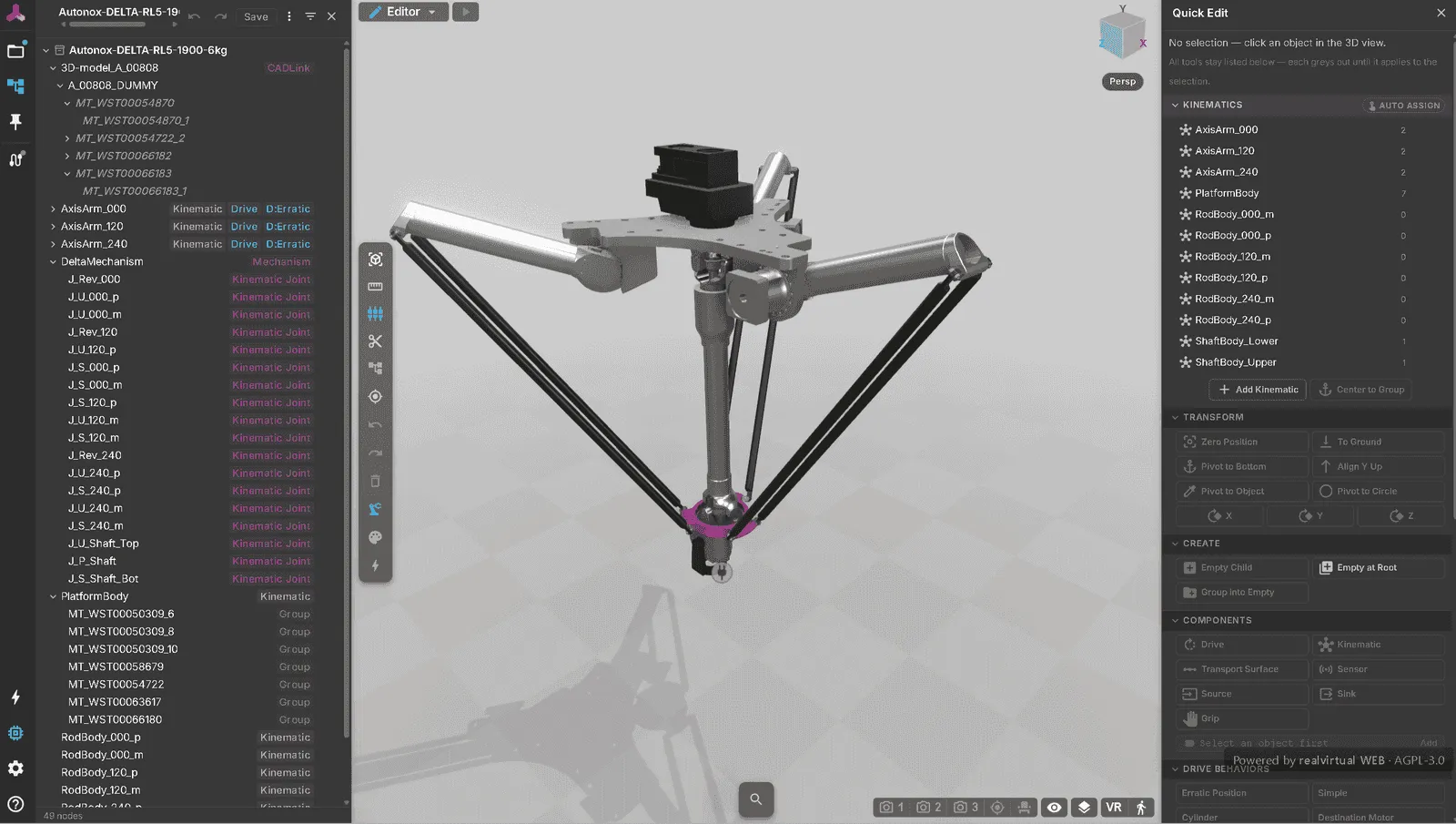
A rigid-body mechanism is a set of links connected by joints that solve together as one system. Unlike a chain of parent-child rotations, this supports closed loops such as four-bar couplers, scissor lifts and Delta platforms. In a closed loop, a link must satisfy two joints at once and cannot be the hierarchy child of both.
Two components make up a mechanism:
- A Mechanism collects every joint in its subtree and runs the solver once per tick. It uses a bounded, damped Newton-Raphson iteration to satisfy every joint simultaneously.
- A Joint is one constraint between two links: Revolute, Prismatic, Spherical or Universal, with an anchor point and axis. Give a joint a Drive and it becomes a boundary condition the mechanism solves around; leave it undriven and the solver works out its value from the others.
An optional third component, a Target, runs the solve backwards. It moves a mechanism’s driven joints so that one of its links follows a point in space. For example, you can move a Delta picker by dragging its platform rather than its three motors.
You get a mechanism one of two ways:
- Build it in Unity. Use
KinematicMechanism,KinematicJointandKinematicTarget(Professional) as you would other kinematics. Export to GLB and the mechanism runs identically in the viewer. Standalone simulation and Live mode both use the same solver as Unity. - Build it in the browser. Use the Mechanism (Rigid-Body) section in Quick Edit to build directly on raw, unkinematized CAD, without a Unity round-trip. Quick Edit is part of the Editor, so browser authoring requires the Editor.
Not the same as Kinematics
Section titled “Not the same as Kinematics”The older Kinematics section in Quick Edit groups parts onto a single moving axis inside the existing hierarchy — the right tool for a hinge, a slide or a turntable. A mechanism instead solves a graph of joints, which is the only way to express a loop that closes back on itself. The two panels are intentionally kept apart and share no components: if what you’re building has one clear moving axis, use Kinematics; if it has a closed loop or several joints that move together, use Mechanism.
Key properties
Section titled “Key properties”Mechanism
Section titled “Mechanism”| Property | Description |
|---|---|
| Solver Iterations | Fixed number of Newton-Raphson iterations per tick (default 4). Kept constant for a deterministic solve. |
| Damping | Damped-least-squares factor that keeps the solve stable near a singular configuration (default 0.01). |
| Tolerance | Constraint residual, in millimeters, below which the solve counts as converged (default 0.001 mm). |
| Converged | Read-only. True when the last solve met the tolerance. |
| Residual Error | Read-only. The largest constraint error left after the last solve, in millimeters. |
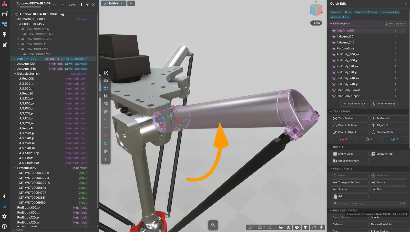
| Property | Description |
|---|---|
| Joint Type | Revolute, Prismatic, Spherical or Universal. Only Revolute and Prismatic have a single scalar value, so only they can carry limits or a Drive. |
| Body A / Body B | The two links the joint connects. Leave Body A empty to anchor the joint in world space. This fixes the mechanism to the machine frame instead of another moving link. Body B is always required. |
| Anchor A / Anchor B | The joint’s pivot point, in each body’s own local space, in millimeters. The two should coincide in world space. |
| Axis A | The joint axis, in Body A’s local space. Unused by Spherical. |
| Secondary Axis B | A second axis in Body B’s local space, used only by Universal joints. |
| Use Limits / Lower / Upper Limit | Clamps the joint value in degrees (Revolute) or millimeters (Prismatic). |
| Driven By | The Drive that moves this joint. Leave it empty for a passive joint the mechanism solves for. |
| Current Value | Read-only. The joint’s live value, written by the solver every tick. |
Target
Section titled “Target”| Property | Description |
|---|---|
| Mechanism | The mechanism whose driven joints this target solves for. |
| Target Link | The mechanism’s own link that should follow this node — a Delta platform, for example. |
| Tracking Active | While on, an inverse solve runs every tick and takes over the mechanism’s Drives. |
| Reachable | Read-only. False when the target is outside the workspace or a limit was hit — the mechanism still moves to the closest pose it can reach. |
Quick Start
Section titled “Quick Start”From Unity
- Build the mechanism with
KinematicMechanismandKinematicJointcomponents, the same way as any Professional kinematics. - Export the scene to GLB.
- Open the model in realvirtual — the mechanism forward-solves exactly as it did in Unity, driven by the same Drives, in both Standalone and Live mode.
From the browser (Quick Edit)
- Import the raw CAD and select the links you want to connect.
- Open Mechanism (Rigid-Body) in Quick Edit and click + Mechanism.
- Add a joint, pick its type, then click Body A and Body B directly in the 3D view. Hover to highlight snap candidates (face centers, edges, circle centers) before you commit. Leaving Body A unset anchors the joint to the world.
- Assign a Drive to the joint you want to move.
- Validate and clear anything the findings list flags.
- Jog the driven joint with its slider and watch the mechanism move under the real solver.
- Save. The mechanism is part of the asset now, ready to place in a layout like any other component.
Assigning a Drive takes effect immediately: the running mechanism picks the Drive up on the next tick, so you can jog the joint straight away without reloading the model.
Snapping also reads curved surfaces. Hovering a bore or a cylindrical wall fits its axis and radius, so a revolute joint lands on the hole’s centerline instead of on the nearest flat feature — and when a bore and the boss around it are both under the cursor, the bore wins.
Validation & Jog
Section titled “Validation & Jog”Every joint with a problem gets a warning next to it, naming the finding it triggered. Findings include a missing Body B, anchors that don’t coincide, and a Drive whose axis doesn’t match the joint. Where a fix is unambiguous, a Snap button applies it directly. Other findings provide a diagnosis without an automatic fix.
The Jog slider runs the actual solver, not a preview animation. The convergence flag and residual reflect runtime behaviour. A configuration that doesn’t converge colors the joint and shows the finding code responsible. This reveals limit conflicts or unreachable anchors while you build, before you save.
Force Analysis and Drive Sizing
Section titled “Force Analysis and Drive Sizing”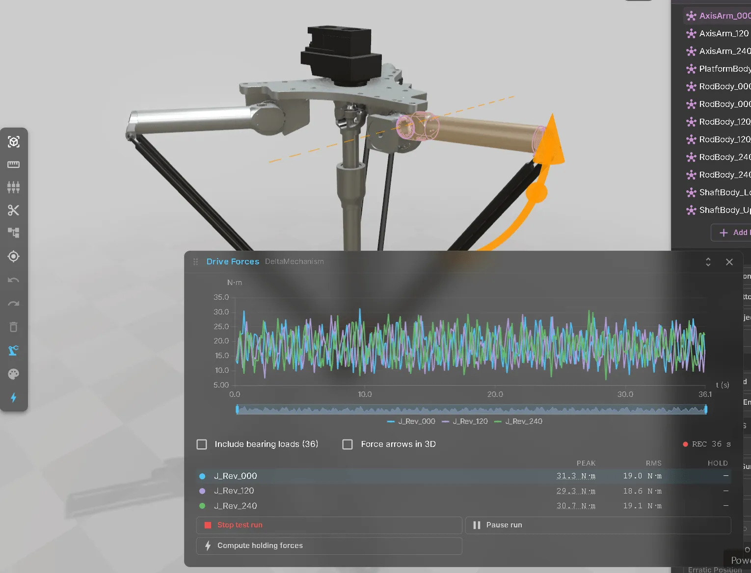
The same solver computes an actuator force or torque for every driven joint and a bearing load for every joint. Force analysis does not affect motion or change any pose.
Give each link a mass
Section titled “Give each link a mass”Force analysis needs to know what it is moving, so every link of the mechanism needs a Body. Open the mechanism in Quick Edit and each link gets a row with an Add Body button:
| Property | Description |
|---|---|
| Density Preset | Steel, aluminum, stainless, PA, POM or a custom value. The mass is computed from the link’s geometry and this density. |
| Mass | Read-only unless pinned. Shows the computed mass and how it was obtained — a value marked (estimated) came from a bounding box because the geometry was not closed. |
| Pin mass | Replaces the computed mass with the value you enter. Use it for a payload, for a part whose CAD is a placeholder, or for a link that carries no geometry at all. |
| COM | The center of mass in the link’s own coordinates. Pin it when the model omits something heavy — a motor, a cable carrier. |
Mass values follow two rules:
- The mass is never guessed silently. If a link’s geometry is open, self-intersecting or missing, the row says so and the value is labeled as an estimate.
- One link without a usable mass switches the analysis off for the whole mechanism, and the findings list says which one. A partial result would mislead: a drive sized for a machine without its heaviest link will not fit.
See where the mass sits
Section titled “See where the mass sits”A centre of mass in a rotated, nested link’s own coordinates is hard to check by eye. The numbers alone do not show whether the position is correct. The mechanism section shows the mass in 3D, with two independent switches in its header:
- Link COMs puts a small marker at every link’s centre of mass. Its style shows the source: filled for a mass computed from closed geometry, hollow for a bounding-box estimate. A pinned value has its own colour. A dashed ring marks a link that belongs to more than one mechanism. The marker’s screen size stays constant regardless of mass or zoom. It shows position, not mass.
- Total COG marks the whole mechanism’s centre of gravity with the quartered-circle symbol used on drawings. It also displays the value beside the switches:
184.62 kg · COG (12.4, 630.1, -3.8) mm · from 7 of 9 links. This is the centre of gravity used for tipping safety, lifting points and floor loading. It follows the mechanism as it moves.
The total reports missing data, estimates and ambiguity:
- It is computed only from links that have a positive mass and a usable centre of mass. The readout counts contributing links (from 7 of 9 links) and names excluded links. Hover to see the reason: no body, no mass, or a pinned mass without geometry and a known centre of mass.
- If any contributing link is an estimate, the total is marked
~estimated. Pinning a centre of mass does not remove the mass’s estimated status. - A link shared between two mechanisms makes the total ambiguous, because each mechanism computes that link’s geometry against its own set of neighbours.
The readout is always there; the markers only while you switch them on. Over MCP, web_query("mechanism.inspect", {}) returns the same figures as cog on every mechanism, together with each link’s comLocalMm, so an agent can check a mass assignment without a screenshot.
Record a cycle
Section titled “Record a cycle”Open Forces under the mechanism and press Test in the editor toolbar. The recording starts with the test run and ends when you stop it. The last cycle stays on screen so you can read it afterwards.
- The chart plots every driven joint at once, with one colour per joint and a legend underneath. It shows actuator torque for a rotary joint and force for a linear one. Include bearing loads adds the bearing series, with their number in brackets.
- Peak is the largest magnitude over the cycle: the load a drive must withstand once.
- RMS is the effective value over the cycle, weighted by real elapsed time: the load a drive must withstand continuously.
- Hold is the holding torque in the current pose. It comes only from Compute holding forces, never from the recording, so the Hold column stays empty during a run. Velocity passing through zero does not mean the machine is standing still.
Both reference lines are drawn on the chart, so you can see at a glance whether a cycle is a short spike on a light duty or a sustained load.
Statics without running
Section titled “Statics without running”Compute holding forces calculates the forces needed to hold the current pose under gravity, with nothing moving. It needs no recording or test run. Use it to check a lifting axis or counterweight while building the machine.
Force arrows in 3D
Section titled “Force arrows in 3D”Tick Force arrows in 3D and every joint gets an arrow along its reaction force. Arrow length is capped, and color shows magnitude. Linear scaling would extend heavily loaded joints’ arrows off screen and make the others too small to see. Hover over an arrow to read its value; click it to select that joint’s series in the chart. The arrows disappear when you leave the editor.
What it does not cover
Section titled “What it does not cover”- The mechanism solver computes no contact, cutting/process or friction forces. With rigid-body physics enabled, Rapier measures contact loads on mechanism links and feeds them into force analysis one simulation step late, shown in the Ext. load column (N). These loads never change poses. Cutting/process forces and friction remain unmodeled. Without physics, you represent a payload as an added mass on the link that carries it.
- Where a mechanism is over-actuated (more drives than degrees of freedom in a loop), the force split is not physically unique. The panel reports this instead of choosing a split between the drives.
- Gravity is standard, along −Y. A tilted installation is not yet configurable.
Smooth (jerk-limited) motion
Section titled “Smooth (jerk-limited) motion”A drive that ramps with a constant acceleration changes that acceleration instantly at the start and end of the ramp. On a real machine that step is what shakes the structure, marks the product and wears the gearbox. Smooth motion replaces the trapezoidal ramp with a jerk-limited S-curve, so acceleration itself rises and falls at a bounded rate.
It is set on the drive, not on the mechanism, and applies just as much to an ordinary axis as to a joint the solver drives:
| Property | Description |
|---|---|
| Use Acceleration | The existing acceleration ramp. Smooth motion is a sub-setting of it and does nothing on its own. |
| Smooth Acceleration | Switches the jerk-limited S-curve on in place of the trapezoidal ramp. |
| Jerk | The rate of change of acceleration, in mm/s³ for linear drives and deg/s³ for rotary ones. Lower is gentler and slower; higher approaches the hard trapezoidal ramp. |
| Speed Override | A factor on this drive’s speed, multiplied with the global simulation speed. It scales the time through the profile rather than the limits, so setting it to 0 pauses and resuming never makes the position jump. |
Unity and the browser share the same numerical core and S-curve implementation. A machine tuned in Unity therefore moves identically here.
Where it is not available, a drive asking for smooth motion keeps running the familiar trapezoidal ramp and the viewer warns once for the model rather than once per drive. The model stays fully usable; it simply does not get jerk limiting. Endless rotary axes that wrap at their limits stay continuous across the wrap either way.
Drive behaviours and travel limits
Section titled “Drive behaviours and travel limits”Any drive can carry a drive behaviour, whether it moves a mechanism joint or an ordinary axis.
Erratic Position moves a drive to random positions between a minimum and a maximum. Use it to keep an axis moving during a demonstration or load test.
Its range is clamped to the drive’s own travel limits. Previously, a range extending beyond those limits left the axis waiting indefinitely for an unreachable position. Now each target is clamped when selected, and the viewer warns you to correct the authored range. Return-to-zero on a falling enable signal is clamped the same way, including when the axis limits exclude zero.
Common Use Cases
Section titled “Common Use Cases”- Scissor Lift Table – A prismatic drive raises a platform through a chain of pivoting links.
- Four-Bar Gripper – A single drive closes both jaws through a coupler link, keeping them synchronized without a second motor.
- Delta Picker – Three arms constrain a platform to a Cartesian workspace; a Target lets you place the platform directly instead of driving each arm.
- Slider-Crank – A rotary drive converts to linear motion (or back), the classic Prismatic + Revolute loop.
See also
Section titled “See also”- Editor — Quick Edit, including the Mechanism and Kinematics sections
- The Interface — filtering the node tree down to drives
- Collision Detection — catching unintended contact once a mechanism moves
- Signals and alarms — how a mechanism’s Drives connect to live signals