
Modbus
Introduction
Section titled “Introduction ”Modbus is a data communications protocol originally published by Modicon (now Schneider Electric) in 1979 for use with its programmable logic controllers (PLCs). Modbus has become a de facto standard communication protocol and is now a commonly available means of connecting industrial electronic devices (Source https://en.wikipedia.org/wiki/Modbus).
Modbus is a very simple standard which is transfering discrete inputs and outputs or registers (double word).
realvirtual.io offers two Modbus components:
- Modbus TCP (ModbusTCPInterface) - the recommended interface with Client and Server mode. Addresses and data types are defined as signal metadata and are identical to realvirtual WEB / CONNECT.
- Modbus TCPRTU (Legacy) (ModbusInterface) - the previous server-only interface with a ModbusData component per signal. Existing scenes keep working unchanged; use the new interface for new projects.
Modbus TCP (Client & Server)
Section titled “Modbus TCP (Client & Server)”Overview
Section titled “Overview”The Modbus TCP interface connects Unity signals with Modbus TCP devices. In Client mode Unity connects to a Modbus device (for example an Inovance H5U / AM600, Wago or Schneider PLC) and reads and writes its coils and registers. In Server mode Unity simulates a Modbus device: external Modbus masters (PLC, HMI, SCADA) connect to Unity, read the PLCInput values and write the PLCOutput values.
Add it with Add Component > realvirtual > Interfaces > Modbus TCP. Signals are child objects of the interface, like with every other realvirtual interface.
Properties
Section titled “Properties”Mode (Client / Server) Selects whether Unity connects to a Modbus device (Client) or lets Modbus masters connect to Unity (Server).
Host (string, Client only) IP address of the Modbus device.
Port (integer) TCP port. In Client mode the port of the device, in Server mode the port Unity listens on. The Modbus default is 502.
Unit Id (byte) Modbus unit identifier (slave ID) of the device.
Word Order (ABCD / CDAB / BADC / DCBA) Register order of 32-bit values (INT, UINT, FLOAT). ABCD is the Modbus standard, many Inovance PLCs use CDAB. A wrong word order produces wrong 32-bit values while 16-bit values are still correct - the most common Modbus integration error.
Connection Timeout Ms (integer, Client only) Connection and response timeout in milliseconds.
Connected Clients (read-only, Server only) Number of Modbus masters currently connected.
Configured Signals / Skipped Signals (read-only) Number of signals with a valid Modbus configuration and number of signals skipped because of an invalid configuration. The Console shows the reason for every skipped signal.
The general settings Update Cycle Ms, Auto Reconnect and Reconnect Interval Seconds work like for every realvirtual FastInterface. PLCInput signals are written to the device when their value changes and completely after every (re)connect. In Client mode a connection without any traffic (only unchanged PLCInputs) is checked every second with a single read, so a restarted device is detected and receives all values again.
Signal addresses
Section titled “Signal addresses”Every signal needs the metadata key ModbusAddress. The optional key ModbusDataType defines the data type; without it Bool signals use BOOL, Int signals SHORT and Float signals FLOAT.
| Address | Table | Offset |
|---|---|---|
C00001 / C0 | Coil (read/write bit) | 0 |
DI10001 / DI0 | Discrete Input (read-only bit) | 0 |
IR30001 / IR0 | Input Register (read-only 16 bit) | 0 |
HR40001 / HR0 | Holding Register (read/write 16 bit) | 0 |
HR40010.3 | Bit 3 of Holding Register offset 9 | 9 |
- Exactly five digits are the classic 1-based notation:
HR40001is holding register offset 0,C00013is coil offset 12. - Every other digit count is the 0-based offset directly:
HR0,HR9,C12. - Offsets from 10000 must be written in six-digit form (
HR012345) or short form -HR12345has five digits and is read as classic notation (offset 2344). - A
.bitsuffix (0-15) addresses a single bit of a holding or input register. Writing such a bit only changes this bit, all other bits of the register are preserved. - The usable offset range is 0 to 65533, including the width of the data type (an INT at
HR065533is rejected).
Data types: BOOL, BYTE, SBYTE, SHORT, USHORT, INT, UINT, FLOAT. INT, UINT and FLOAT use two registers and the configured word order. UINT values are kept as 32-bit bit pattern in Int signals, so 0xFFFFFFFF appears as -1.
Direction rules:
| Mode | PLCOutput (Unity reads) | PLCInput (Unity writes) |
|---|---|---|
| Client | C, DI, IR, HR | C, HR |
| Server | C, HR (written by the master) | C, DI, IR, HR |
A signal that breaks a rule (for example a PLCInput on an input register in Client mode) is logged in the Console and skipped.
Quick Start
Section titled “Quick Start”- Add an empty GameObject and the component Modbus TCP.
- Select the Mode, enter Host (Client) and Port and set the Word Order of your device.
- Create PLCInput / PLCOutput signals as children of the interface and add the metadata ModbusAddress (and optionally ModbusDataType) - or use Import Signals from CSV.
- Press Validate Addresses to check all signals.
- Start the simulation - the interface connects (Client) or starts listening (Server).
CSV import
Section titled “CSV import”Import Signals from CSV reads a semicolon separated file with one signal per row:
Name;Direction;Type;Address;DataTypeStart;Input;Bool;C00001;Speed;Output;Float;HR40010;FLOATCount;Output;Int;IR30001;UINTDirection is Input or Output, Type is Bool, Int or Float, DataType is optional. Missing signals are created, existing signals with the same name get the new metadata (no duplicates). Invalid rows are logged and skipped. The import supports Undo.
Inovance PLCs
Section titled “Inovance PLCs”Inovance H5U / Easy and AM400 / AM600 / AC800 controllers support Modbus TCP. Their 32-bit values usually use the word order CDAB. Check the Modbus address mapping of your controller (for example D registers to holding registers) in the Inovance documentation and use the six-digit form for offsets from 10000.
Troubleshooting
Section titled “Troubleshooting”- “Port … is in use or blocked by firewall” (Server mode): another program or another Modbus server already uses the port, or the firewall blocks it. Choose a different port or stop the other program. With Auto Reconnect the server starts automatically as soon as the port is free. In the rare case that another program takes the port exactly while the server starts, an additional red error of the EasyModbus listener appears in the Console and Connected Clients stays 0.
- Wrong 32-bit values: check the Word Order (ABCD vs. CDAB).
- Skipped Signals > 0: the Console lists every skipped signal with the reason; Validate Addresses repeats the check in edit mode.
Common Use Cases
Section titled “Common Use Cases”- Virtual commissioning – test a Modbus TCP PLC program against the Unity simulation (Client mode).
- Device simulation – let an HMI or SCADA system connect to a simulated Modbus device (Server mode).
- Loopback test – connect two Unity interfaces (Client and Server) to test a signal table without hardware.
Modbus TCPRTU (Legacy)
Section titled “Modbus TCPRTU (Legacy)”Modbus master
Section titled “Modbus master”If realvirtual.io is acting as a Modbus master the clients need to poll and write their values to realvirtual.io. The modbus master is not acting actively on his own. The Modbus server is always on the computers IP adress woth the standard port 502.
Interface configuration
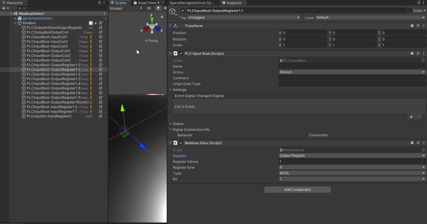
Section titled “Interface configuration”The legacy Modbus interface is added to the Scene with Add Component > realvirtual > Interfaces > Modbus TCPRTU (Legacy) or by adding the script ModbusInterface to an empty GameObject.
Because Modbus is only transferring discrete inputs or outputs or words and because there is no standard data structure for describing the content inside these data you need to define how to interpret the Modbus data inside realvirtual.io.
Each PLCInput or PLCOuput signal needs to hava an attached ModbusData component. This component is defining with its properties how the bits and bytes should be interpreted by realvirtual.io.
See Also
Section titled “See Also”© 2025 realvirtual GmbH https://realvirtual.io - All rights reserved. No part of this publication may be reproduced, distributed, or transmitted in any form or by any means, including printing, saving, photocopying, recording, or other electronic or mechanical methods, without the prior written permission of the publisher.\