
Drive Position Switch
Overview
Section titled “Overview”The Drive Position Switch component controls a boolean PLC signal based on the drive’s position. It monitors one or more position ranges and activates an output signal when the drive enters any of these areas. The component fully supports both linear and rotational drives, including drives with wrap-around behavior (e.g., 0-360° rotational drives).
This component is particularly useful for creating position-dependent logic in automation systems, such as activating sensors, triggering actions at specific zones, or creating safe areas on linear or rotational axes.
Key Features
Section titled “Key Features”- Multiple Position Areas - Define multiple ranges where the signal should be active
- OR Logic - Signal activates when drive is in ANY defined area
- Area Inversion - Optionally define areas as “false zones” instead of “true zones”
- Position Offset - Apply a global offset to the drive position before checking areas
- Wrap-Around Support - Automatic detection and handling of rotational drives with position wrapping
- Wrapped Areas - Support for areas that wrap around limits (e.g., 350-10° on a 0-360° drive)
Properties
Section titled “Properties”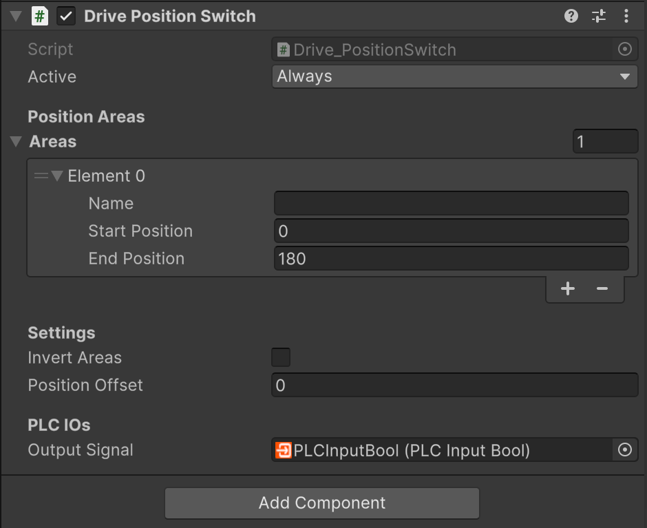
Drive Position Switch Inspector
Position Areas
Section titled “Position Areas”Areas (list) A list of position ranges that control the output signal. Each area has:
- Name - Descriptive name for the area
- Start Position - Beginning of the range in millimeters or degrees
- End Position - End of the range in millimeters or degrees
When the drive position is within ANY of these areas, the output signal is set to true (OR logic). For rotational drives with wrapping enabled, areas can wrap around the limits by setting Start Position > End Position (e.g., 350-10 on a 0-360° drive).
Settings
Section titled “Settings”Invert Areas (boolean) When enabled, the defined areas become “false zones” instead of “true zones”. The output signal is false when inside areas and true when outside all areas. This is useful for defining exclusion zones or safe areas.
Position Offset (float) A global offset in millimeters or degrees applied to the drive’s current position before checking areas. For drives with wrapping enabled, the offset is automatically normalized to stay within the drive’s limits. This allows you to shift all areas without modifying each individual area range.
PLC IOs
Section titled “PLC IOs”Output Signal (PLCInputBool) The boolean signal sent to the PLC. This signal is true when the drive position (after applying offset) is within any defined area, or inverted if Invert Areas is enabled. Connect this to your PLC logic or other components that need position-based triggering.
Basic Position Switch
Section titled “Basic Position Switch”To create a simple position switch that activates in specific zones:
- Add a Drive component to a GameObject
- Add the Drive Position Switch component to the same GameObject
- In the Inspector, expand the Areas list and click the + button
- Set Start Position and End Position for your desired activation zone
- Add a PLCInputBool signal or connect the Output Signal to your logic
- The signal will be true when the drive is within the defined range
Multiple Zones
Section titled “Multiple Zones”To activate the signal in multiple separate zones:
- Add multiple elements to the Areas list
- Configure each area with different Start and End positions
- The output will be true if the drive is in ANY of the defined areas (OR logic)
Example: Activate signal at positions 100-150mm and 300-350mm:
- Area 1: Start=100, End=150
- Area 2: Start=300, End=350
Rotational Drives with Wrap-Around
Section titled “Rotational Drives with Wrap-Around”For rotational drives that jump from upper to lower limit (e.g., 360° to 0°):
- Ensure your Drive has Use Limits enabled and Jump To Lower Limit On Upper Limit enabled
- Create areas that can wrap around limits by setting Start Position > End Position
- The component automatically detects and handles wrapped areas
Example: Activate between 350° and 10° on a 0-360° drive:
- Area: Start=350, End=10
- Signal will be true from 350° to 360° AND from 0° to 10°
Safe Zones with Area Inversion
Section titled “Safe Zones with Area Inversion”To define safe zones where the signal is false (and true everywhere else):
- Enable Invert Areas checkbox
- Define areas where you want the signal to be FALSE
- The output will be true when OUTSIDE all defined areas
Example: Create a safe zone from 100-200mm where output is false:
- Enable Invert Areas
- Area: Start=100, End=200
- Result: Signal is false from 100-200mm, true everywhere else
Position Offset
Section titled “Position Offset”Use position offset to shift the coordinate system without modifying all areas:
- Set Position Offset to your desired offset value
- The drive’s position is adjusted before checking areas
- For wrapping drives, the offset is automatically normalized
Example: Check if drive is at position 0-50mm with 100mm offset:
- Area: Start=0, End=50
- Position Offset: 100
- Result: Signal is true when drive is at -100 to -50mm (adjusted to 0-50mm)
See Also
Section titled “See Also”- Drive - The main Drive component
- Drive Behaviors - Overview of all Drive Behavior components
- PLCInputBool - Boolean signals to PLC
- Sensor - Alternative for proximity-based detection