
RFSuite (Pro)
RF::Suite Interface Overview
The RF::Suite interface facilitates seamless communication between Winmod and realvirtual.io, particularly beneficial for virtual commissioning tasks, notably in automotive production.For more information about RF::Suite please check:
The interface relies on shared memory, necessitating both RF::Suite and realvirtual.io to operate on the same Windows computer. This ensures optimal compatibility and efficient data exchange.
Interface properties
Section titled “Interface properties”SHMName:
- Specifies the name of the Shared memory. This needs to be set to the same value as in the RF::Suite application
ImportSymbolTable:
- Specifies the symbol table utilized for signal importation. To select a table, click the “Select symbol table” button. After selecting the table, you can import it and create signals during runtime by clicking “Import symbol table”.
RegExNotImportSymbolNames:
- Specifies a list of regular expressions for excluding specific symbol names from signal importation.
SHMSize:
- Indicates the size of the shared memory utilized by the interface.
Status
- Reflects the status of the interface during simulation.
NumInputs and NumOutputs:
- Provide information on the number of input and output signals configured within the interface, respectively.
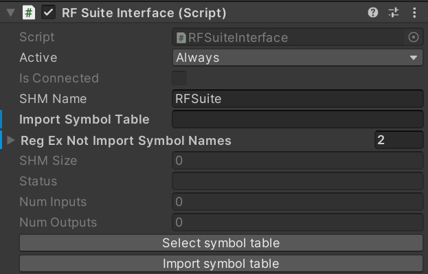
RFSuite interface properties
Importing Signals
Section titled “Importing Signals”Signals can be conveniently imported using a .txt file, exported directly from RF::Suite applications. It’s imperative to adhere to a specific table format, precisely matching the column headers as outlined in the example provided. For selecting and importing Signals you need to use the buttons “Select symbol table” and “Import symbol table”
Here is an example for the signal import table:
Line number Driver Signal Symbol Address Datatype Default Value Comment1 XE 0.0 YE_ReserveBit_1 XE 0.0 bool VISU Input Reserve Bool 12 XE 0.1 YE_ReserveBit_2 XE 0.1 bool VISU Input Reserve Bool 23 XE 0.2 YE_ReserveBit_3 XE 0.2 bool VISU Input Reserve Bool 34 XE 0.3 YE_ReserveBit_4 XE 0.3 bool VISU Input Reserve Bool 45 XE 0.4 YE_ReserveBit_5 XE 0.4 bool VISU Input Reserve Bool 56 XE 0.5 YE_ReserveBit_6 XE 0.5 bool VISU Input Reserve Bool 6Manually Setting Up Signals
Section titled “Manually Setting Up Signals”For manual signal configuration, it’s essential to define the signal’s position within the Shared Memory Area. This involves appending a memory position description to the signal name, following a standardized convention detailed below:
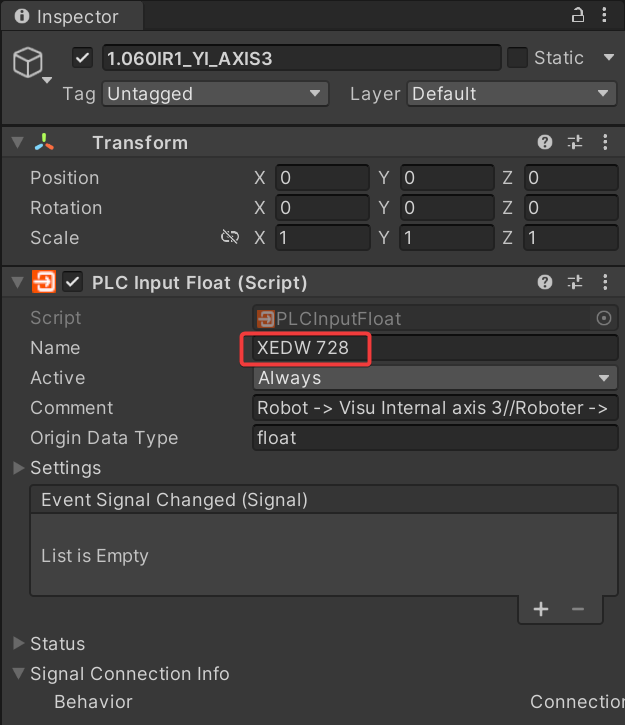
Defining the memory position for a signal
- For Outputs: Use “XA” as the first two letters.
- For Inputs: Utilize “XE” as the initial two letters.
- Signal Data Types:
- Boolean: Example format - “XE 13.6”
- Int8: Example format - “XEB 27”
- Int16: Example format - “XEW 160”
- Int32: Example format - “XEDW 200”
- Float: Example format - “XEDW573”