
Beckhoff TwinCAT
Introduction
Section titled “Introduction”This scene is a virtual commissioning setup for testing and validation with real or virtual Beckhoff PLCs programmed using TwinCAT. The PLC controls the process flow, including starting the robot, while the robot controller is fully simulated. It enables safe and flexible testing of automation logic without the need for real hardware. For prerequisites and setup instructions, please visit https://doc.realvirtual.io/modellzoo.
This document lists all signals exchanged between realvirtual (Unity) and a Beckhoff TwinCAT PLC for controlling the TwinCAT Demo, following the convention that IO.Input = PLC Input (from realvirtual) and IO.Output = PLC Output (from PLC). The tables below map each signal to its purpose in the modelzoo simulation.
Prerequisites
Section titled “Prerequisites”To use the Beckhoff ModelZoo scene, you will need an installation of Beckhoff TwinCAT 3 (recommended version: 3.1.x or higher). You can connect either a real PLC or use the local TwinCAT PLC runtime (PLCSim) on your PC.
For communication with the PLC, TwinCAT 3 ADS (usually part of a full TwinCAT3 installation) must be installed on the same PC where the realvirtual.io ModelZoo is running. Make sure TwinCAT is in Run mode, and that the correct AMS NetID and port are configured in the simulation settings.
We provide a complete TwinCAT project for this scene, which can be imported and compiled directly in the TwinCAT environment.
Ready-to-Run Beckhoff Project
Section titled “Ready-to-Run Beckhoff Project”For this ModelZoo scene, we provide a complete Beckhoff TwinCAT project.
You can import, compile, and run it directly within the TwinCAT environment to control the simulation seamlessly.
Interface Configuration
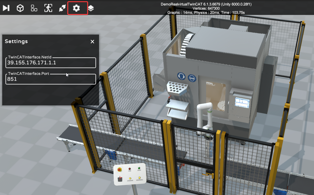
Section titled “Interface Configuration”Before connecting to a Beckhoff PLC, you need to configure the NetID and Port used for communication.
To do this:
- Click the Settings icon (⚙️) in the toolbar.
- Enter your TwinCATInterface.NetId and TwinCATInterface.Port as shown in the image below.
- Make sure the values match your TwinCAT runtime setup.
📘 Refer to the official Beckhoff documentation for details on how to find or configure your NetID and Port.
Signals
Section titled “Signals”1. Robot Signals
Section titled “1. Robot Signals”1.1 Robot Overall Status
Section titled “1.1 Robot Overall Status”These signals tell the PLC whether the robot is in a loading or unloading state, as determined by the realvirtual simulation.
| Signal | Type | Direction | Description |
|---|---|---|---|
IO.Input.Robot.bStatusLoading | BOOL | realvirtual → PLC (In) | Indicates that the robot is currently loading a part |
IO.Input.Robot.bStatusUnloading | BOOL | realvirtual → PLC (In) | Indicates that the robot is currently unloading a part |
1.2 Start Robot Programs
Section titled “1.2 Start Robot Programs”These signals come from the PLC and are used by realvirtual to trigger robot actions in the simulation.
| Signal | Type | Direction | Description |
|---|---|---|---|
IO.Output.Robot.bStartLoading | BOOL | PLC → realvirtual (Out) | When set by the PLC, requests the robot to start loading. |
IO.Output.Robot.bStartUnloading | BOOL | PLC → realvirtual (Out) | When set by the PLC, requests the robot to start unloading. |
2. Machine Signals
Section titled “2. Machine Signals”These signals handle the interaction between the simulated machine (e.g., a milling station) and the PLC.
| Signal | Type | Direction | Description |
|---|---|---|---|
IO.Output.Machine.bStart | BOOL | PLC → realvirtual (Out) | When set by the PLC, starts the machine operation in the simulation. |
IO.Input.Machine.bMachining | BOOL | realvirtual → PLC (In) | Tells the PLC that the machine is currently machining |
IO.Input.Machine.bMachiningFinished | BOOL | realvirtual → PLC (In) | Tells the PLC the machine has finished its operation |
IO.Input.Machine.bDoorOpen | BOOL | realvirtual → PLC (In) | Indicates the machine door is open in the simulation. |
IO.Input.Machine.bDoorClosed | BOOL | realvirtual → PLC (In) | Indicates the machine door is closed in the simulation. |
3. Entry and Exit Conveyor
Section titled “3. Entry and Exit Conveyor”3.1 Exit Belt Signals
Section titled “3.1 Exit Belt Signals”| Signal | Type | Direction | Description |
|---|---|---|---|
IO.Output.ExitBelt.Motor.bStart | BOOL | PLC → realvirtual (Out) | PLC requests the simulation to start the exit conveyor motor. |
IO.Input.ExitBelt.Sensor.bOccupied | BOOL | realvirtual → PLC (In) | Simulation indicates whether the exit belt sensor is triggered/occupied. |
3.2 Entry Belt Signals
Section titled “3.2 Entry Belt Signals”| Signal | Type | Direction | Description |
|---|---|---|---|
IO.Output.EntryBelt.Motor.bStart | BOOL | PLC → realvirtual (Out) | PLC requests the to start the entry conveyor motor. |
IO.Input.EntryBelt.Sensor.bOccupied | BOOL | realvirtual → PLC (In) | Simulation indicates whether the entry belt sensor is triggered/occupied. |
4. HMI (Buttons & Lights)
Section titled “4. HMI (Buttons & Lights)”These signals correspond to the simulated HMI panel. Some are set by the simulation and read by the PLC (Inputs), while others are set by the PLC and read by the simulation (Outputs).
| Signal | Type | Direction | Description |
|---|---|---|---|
IO.Input.HMI.OnSwitch.bOn | BOOL | realvirtual → PLC (In) | Simulation indicates the main HMI switch is turned on. |
IO.Input.HMI.Emergency.bOn | BOOL | realvirtual → PLC (In) | Simulation indicates an emergency button is pressed. |
IO.Input.HMI.AutomaticButton.bPressed | BOOL | realvirtual → PLC (In) | Simulation indicates an “Automatic” button press event. |
IO.Output.HMI.AutomaticButton.bLight | BOOL | PLC → realvirtual (Out) | Turns the Lamp of the button on. |
IO.Input.HMI.Robot.bOn | BOOL | realvirtual → PLC (In) | Simulation indicates the robot button is pressed. |
IO.Input.HMI.EntryBelt.bOn | BOOL | realvirtual → PLC (In) | Simulation indicates the entry belt button is pressed. |
IO.Input.HMI.ExitBelt.bOn | BOOL | realvirtual → PLC (In) | Simulation indicates the exit belt button is pressed. |
IO.Output.HMI.Robot.bLight | BOOL | PLC → realvirtual (Out) | Turns the Lamp of the button on. |
IO.Output.HMI.EntryBelt.bLight | BOOL | PLC → realvirtual (Out) | Turns the Lamp of the button on. |
IO.Output.HMI.ExitBelt.bLight | BOOL | PLC → realvirtual (Out) | Turns the Lamp of the button on. |
5. TwinCAT Configuration
Section titled “5. TwinCAT Configuration”- Match Each Signal
In your TwinCAT PLC project, create variables for every one of the signals listed here. Ensure the variable names match exactly (case-sensitive) and the types are allBOOLunless otherwise specified. - Map to Physical or Virtual I/O
- If connected to real hardware, map these PLC variables to the corresponding digital inputs/outputs.
- For pure simulation, keep them as internal variables in the TwinCAT PLC.
- Enable ADS
Make sure the AMS Router and ADS settings in TwinCAT are configured so Unity/realvirtual can connect. You will need the AMS Net ID and Port in your Unity project. - Configure realvirtual
- In Unity, locate the TwinCATInterface (or similar script).
- Enter the correct ADS settings (Net ID, IP Address, Port).
- Assign each of the “IO.Input” and “IO.Output” strings to the matching TwinCAT variable.