
Mitsubishi McpX (Pro)
The Mitsubishi McpX interface provides high-performance communication with Mitsubishi PLCs using the MC Protocol 3E/4E frames through the McpX library.
Overview
Section titled “Overview”The Mitsubishi McpX interface enables real-time bidirectional data exchange between Unity simulations and Mitsubishi Q, L, R, iQ-R, and iQ-F series PLCs. This Professional-only interface utilizes the MC Protocol (MELSEC Communication Protocol) with 3E/4E frame formats for robust industrial communication. A key feature is its intelligent batch read optimization that automatically groups signals into efficient read operations, reducing network traffic and improving throughput by up to 30x compared to individual signal reads.
The interface supports all major Mitsubishi device types including physical inputs/outputs (X/Y), internal relays (M), data registers (D), timers (T), counters (C), state relays (S), and special devices (SM/SD). Communication runs in a background thread using the FastInterface architecture, ensuring smooth Unity performance while maintaining reliable PLC connectivity.
Installation
Section titled “Installation”The Mitsubishi McpX interface is included in realvirtual Professional and can be added to your scene through:
- Menu Method: Select Tools > realvirtual > Add Interface > Mitsubishi McpX (Pro)
- Manual Method: Add the
MitsubishiMcpXInterfacescript to an empty GameObject
The interface files are located at: Assets/realvirtual/Interfaces/Mitsubishi/
Properties
Section titled “Properties”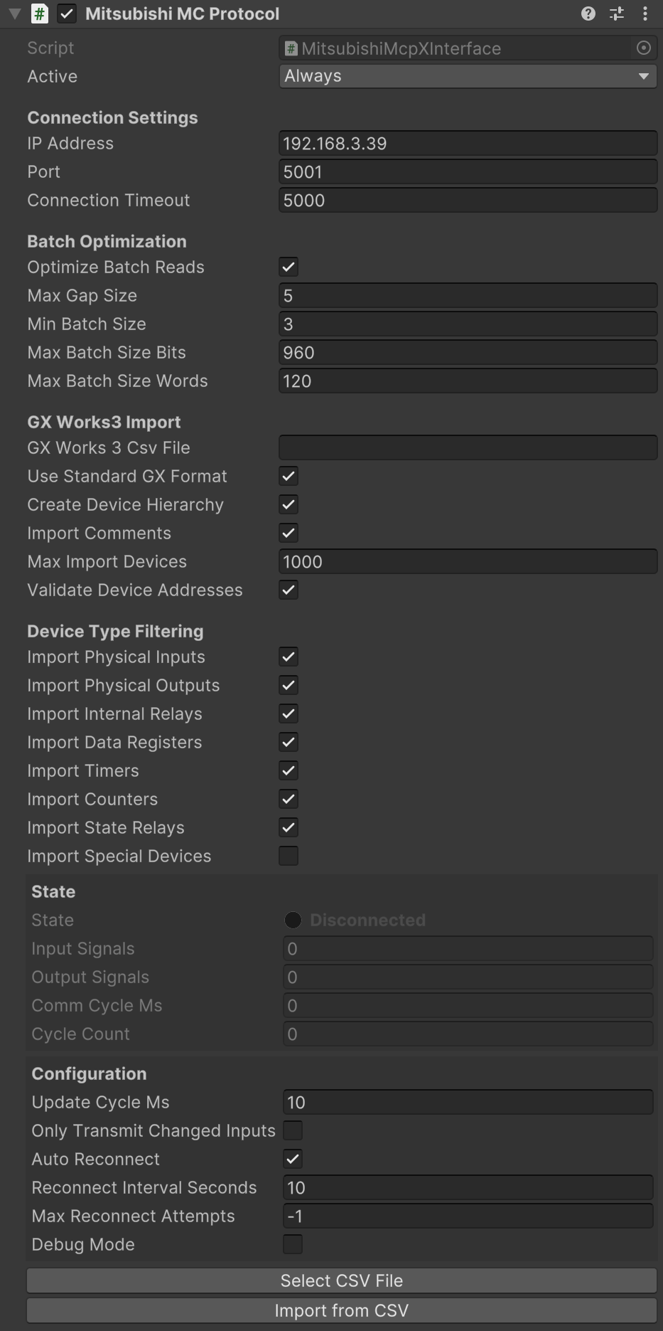
Mitsubishi McpX Interface Inspector
Connection Settings
Section titled “Connection Settings”- IP Address (string): IP address of the Mitsubishi PLC. Default: “192.168.3.39”
- Port (int): MC Protocol communication port. Default: 5001 (standard port for MC Protocol 3E/4E frames)
- Connection Timeout (int): Maximum connection establishment time in milliseconds. Default: 5000
Batch Optimization
Section titled “Batch Optimization”Dramatically improves communication efficiency by grouping multiple signal reads into single network operations, providing up to 30x performance improvement.
- Optimize Batch Reads (boolean): Enables automatic signal grouping for efficient reading. Default: true
- Max Gap Size (int): Maximum address gap between signals in the same batch. Default: 5
- Min Batch Size (int): Minimum signals required to justify batch reading. Default: 3
- Max Batch Size Bits (int): Maximum batch size for bit devices (X, Y, M, etc.). Default: 960 (MC Protocol limit)
- Max Batch Size Words (int): Maximum batch size for word devices (D, W, R, etc.). Default: 120 (MC Protocol limit)
GX Works3 Import
Section titled “GX Works3 Import”Provides seamless integration with GX Works3 device comment exports for rapid signal configuration.
- GX Works3 CSV File (string): Path to device comment CSV export file. Use Select CSV File button to browse
- Use Standard GX Format (boolean): Uses standard GX Works3 CSV format (Device,Comment,Data Type,Initial Value). Default: true
- Create Device Hierarchy (boolean): Organizes imported signals by device type (Physical Inputs (X), Physical Outputs (Y), etc.). Default: true
- Import Comments (boolean): Uses device comments as signal names for meaningful identification. Default: true
- Max Import Devices (int): Safety limit for imported devices to prevent memory issues. Default: 1000
- Validate Device Addresses (boolean): Checks device addresses for validity before import. Default: true
Device Type Filtering
Section titled “Device Type Filtering”Controls which device types are imported from CSV files.
- Import Physical Inputs (boolean): Import X devices (sensors, buttons, switches). Default: true
- Import Physical Outputs (boolean): Import Y devices (actuators, lights, valves). Default: true
- Import Internal Relays (boolean): Import M devices (internal memory bits). Default: true
- Import Data Registers (boolean): Import D devices (16-bit data storage). Default: true
- Import Timers (boolean): Import T devices (timer current values and contacts). Default: true
- Import Counters (boolean): Import C devices (counter current values and contacts). Default: true
- Import State Relays (boolean): Import S devices (state/step relays). Default: true
- Import Special Devices (boolean): Import SM/SD devices (system special relays and registers). Default: false
PLC Configuration
Section titled “PLC Configuration”Enabling MC Protocol
Section titled “Enabling MC Protocol”Configure your Mitsubishi PLC to accept MC Protocol connections:
- GX Works3 Configuration:
- Open your project in GX Works3
- Navigate to Project > Parameter > Ethernet Configuration
- Enable MC Protocol on port 5001 (standard port for 3E frames)
- Set communication data code to Binary (required for 3E frame format)
- Configure allowed operations (Read/Write)
- Network Settings:
- Ensure PLC and Unity PC are on the same network
- Configure IP address and subnet mask appropriately
- Test connectivity with ping command
- Security Settings:
- MC Protocol typically doesn’t require authentication
- Ensure firewall allows communication on configured port
- Some PLCs may require enabling external communication
Device Comment Export
Section titled “Device Comment Export”To export device comments from GX Works3 for import:
-
Export Process:
- Open your GX Works3 project
- Navigate to Project > Export > Device Comment
- Select CSV format
- Choose devices to export
- Save with meaningful filename
-
CSV Format:
Device,Comment,Data Type,Initial ValueX0,Start Button,Bit,0Y0,Motor Output,Bit,0D100,Speed Setpoint,Word[Signed],0M100,System Ready,Bit,0
Optional InputOutput Column
Section titled “Optional InputOutput Column”The CSV import supports an optional InputOutput column that allows you to override the default signal direction for each device. This is useful when the standard device-type-based direction doesn’t match your application requirements.
Supported column headers: InputOutput, Input/Output, or IO (case-insensitive)
CSV Format with InputOutput column:
Device,Comment,Data Type,Initial Value,InputOutputD0,Rx000,Word[Signed],0,InputD1,Rx001,Word[Signed],0,OutputD2,Rx002,Word[Signed],0,M0,System Flag,Bit,0,OutputBehavior:
- Column present with value: The specified direction (“Input” or “Output”) overrides the default
- Column present but empty: Uses the default direction based on device type
- Column not present: Uses the default direction based on device type
Default directions by device type (from PLC perspective):
| Device Type | Default Direction | Description |
|---|---|---|
| X | Input | PLC inputs (sensors) - Unity simulates sensors, sends to PLC |
| Y | Output | PLC outputs (actuators) - PLC sends commands to Unity |
| M, D, T, C, S | Output | Most devices default to reading from PLC |
| SM, SD | Output | Special devices are read-only from PLC |
Manual Signal Creation
Section titled “Manual Signal Creation”For precise control over signal configuration, you can manually create individual PLC signals. The interface automatically parses device type and address from the signal name.
Basic Setup Process
Section titled “Basic Setup Process”- Add Interface to Scene:
- Create an empty GameObject and name it “MitsubishiPLC”
- Add the MitsubishiMcpXInterface component
- Configure the connection settings (IP address and port)
- Create Signal GameObject:
- Right-click the interface GameObject in the hierarchy
- Select Create Empty to add a child GameObject
- Name it descriptively (e.g., “ConveyorStartButton”, “MotorSpeedSetpoint”, “SystemReady”)
- Add Signal Component:
- Select the signal GameObject
- Add the appropriate PLC signal component based on device type:
- PLCInputBool - Send boolean values to PLC (for X devices - sensors)
- PLCOutputBool - Read boolean values from PLC (for Y, M devices - actuators, flags)
- PLCInputFloat - Send numeric values to PLC (for D devices used as setpoints)
- PLCOutputFloat - Read numeric values from PLC (for D devices - status values)
- Configure Signal Properties:
- Name: Set to the Mitsubishi device format (e.g., “X100”, “D200”, “M5”)
- Comment: Add documentation describing the signal purpose
Signal Configuration Examples
Section titled “Signal Configuration Examples”| GameObject Name | Signal Name | Signal Component | Direction | Comment |
|---|---|---|---|---|
| ConveyorStartButton | X0 | PLCInputBool | Input | Sensor → PLC |
| MotorContactor | Y0 | PLCOutputBool | Output | PLC → Actuator |
| SystemReady | M100 | PLCOutputBool | Output | Read flag from PLC |
| SpeedSetpoint | D200 | PLCInputFloat | Input | Send setpoint to PLC |
| ActualSpeed | D201 | PLCOutputFloat | Output | Read value from PLC |
| DelayTimer | T0 | PLCOutputBool | Output | Timer status from PLC |
Configuration Summary
Section titled “Configuration Summary”- GameObject Name: Descriptive name for easy identification in Unity hierarchy
- Signal Name: Mitsubishi device format (X100, D200, etc.) - used for PLC communication
- Comment: Additional documentation about the signal’s purpose and usage
CSV Import
Section titled “CSV Import”The CSV import feature allows rapid signal creation from GX Works3 device comment exports, dramatically reducing setup time for large systems.
Preparing CSV File in GX Works3
Section titled “Preparing CSV File in GX Works3”-
Export Device Comments:
- Open your GX Works3 project
- Navigate to Project > Export > Device Comment
- Select CSV format from the export options
- Choose the device ranges to export
- Save to a location accessible from Unity
-
Verify CSV Format: The exported CSV should follow this structure:
Device,Comment,Data Type,Initial ValueX0,Start Button,Bit,0X1,Stop Button,Bit,0Y0,Motor Contactor,Bit,0Y1,Status Light,Bit,0D100,Speed Setpoint,Word[Signed],1500D101,Temperature Reading,Word[Signed],0M0,System Ready,Bit,0M1,Auto Mode Active,Bit,0
Import Process in Unity
Section titled “Import Process in Unity”- Select CSV File:
- In the Mitsubishi McpX Interface Inspector
- Click the Select CSV File button
- Navigate to your exported CSV file
- Click Open to load the file path
- Configure Import Settings:
- Use Standard GX Format: Keep enabled for GX Works3 exports
- Create Device Hierarchy: Enable to organize signals by device type
- Import Comments: Enable to use device comments as signal names
- Max Import Devices: Set safety limit (default 1000)
- Validate Device Addresses: Keep enabled to catch errors
- Filter Device Types: Enable only the device types you need:
- Physical Inputs (X): Sensors, buttons, switches
- Physical Outputs (Y): Actuators, lights, valves
- Internal Relays (M): Logic flags and status bits
- Data Registers (D): Numeric values and parameters
- Timers (T): Timer current values and contacts
- Counters (C): Counter values and contacts
- State Relays (S): Step sequence control
- Special Devices (SM/SD): Usually disabled
- Execute Import:
- Click the Import from CSV button
- Monitor the Unity Console for import progress and any warnings
- Review created signals in the hierarchy
Post-Import Organization
Section titled “Post-Import Organization”After successful import, you’ll have:
- Organized hierarchy: Signals grouped by device type (if enabled)
- Named signals: Using device comments for meaningful names
- Configured addresses: All device types and addresses set correctly
- Ready-to-use signals: Immediately available for connection to simulation components
Import Validation and Troubleshooting
Section titled “Import Validation and Troubleshooting”Common CSV Issues:
- Encoding problems: Ensure CSV is saved as UTF-8
- Format mismatches: Verify column order matches GX Works3 standard
- Invalid addresses: Check for typos in device addresses
- Large imports: Consider splitting very large files into smaller segments
Post-Import Verification:
- Check Unity Console for any import warnings or errors
- Verify signal names match your expectations
- Test connectivity with a few sample signals before connecting all components
- Review batch optimization settings for optimal performance with your signal layout
Troubleshooting
Section titled “Troubleshooting”Connection Issues
Section titled “Connection Issues”Cannot connect to PLC:
- Verify PLC IP address is correct
- Check MC Protocol is enabled on PLC
- Test with ping command:
ping 192.168.3.39 - Verify firewall settings allow port 5001
- Check network cable and switches
Connection timeouts:
- Increase Connection Timeout value
- Reduce batch sizes if using optimization
- Check network latency
- Verify PLC scan time isn’t too long
Import Issues
Section titled “Import Issues”CSV import fails:
- Verify CSV format matches GX Works3 standard
- Check file encoding (UTF-8 recommended)
- Ensure device addresses are valid
- Review console log for specific errors
Signals not updating:
- Verify PLC is in RUN mode
- Check signal direction: X devices should be Input (Unity → PLC), Y devices should be Output (PLC → Unity)
- Ensure device addresses match PLC program
- Review batch optimization settings
Performance Issues
Section titled “Performance Issues”Slow update rates:
- Enable batch optimization
- Adjust Max Gap Size for better grouping
- Increase Min Batch Size to reduce operations
- Check network bandwidth and latency
Unity freezes during communication:
- Interface runs in background thread
- Check for exceptions in console
- Verify reasonable number of signals (<5000)
- Consider splitting into multiple interfaces
Supported Device Types
Section titled “Supported Device Types”The interface supports all standard Mitsubishi device types:
| Device | Description | Data Type | Address Range |
|---|---|---|---|
| X | Physical Inputs | Bit | X0-X7FF (hex) |
| Y | Physical Outputs | Bit | Y0-Y7FF (hex) |
| M | Internal Relays | Bit | M0-M8191 |
| L | Latch Relays | Bit | L0-L8191 |
| F | Annunciator | Bit | F0-F2047 |
| V | Edge Relays | Bit | V0-V2047 |
| B | Link Relays | Bit | B0-B1FFF (hex) |
| D | Data Registers | Word | D0-D12287 |
| W | Link Registers | Word | W0-W1FFF (hex) |
| T | Timer Contacts/Current | Bit/Word | T0-T511 |
| C | Counter Contacts/Current | Bit/Word | C0-C255 |
| S | State Relays | Bit | S0-S4095 |
| SM | Special Relays | Bit | SM0-SM2047 |
| SD | Special Registers | Word | SD0-SD2047 |
| R | File Registers | Word | R0-R32767 |
| ZR | File Registers | Word | ZR0-ZR65535 |
See Also
Section titled “See Also”- Signal Manager - Managing and organizing signals
- Signal Importer Exporter - Import and export signal configurations
- Custom Interfaces - Creating custom interfaces
- S7 TCP - Similar interface for Siemens PLCs
External Resources
Section titled “External Resources”- McpX Library GitHub - MC Protocol implementation
- Mitsubishi MC Protocol Manual - Official protocol documentation
- GX Works3 Documentation - PLC programming software
© 2025 realvirtual GmbH https://realvirtual.io - All rights reserved. No part of this publication may be reproduced, distributed, or transmitted in any form or by any means, including printing, saving, photocopying, recording, or other electronic or mechanical methods, without the prior written permission of the publisher.