
KUKA (Pro)
The KUKA Interface component provides TCP/IP communication with KUKA OfficeLite virtual controllers using the Y200 protocol through the OpenCommissioning OC_Assistant_OfficeLite server. This integration enables real-time exchange of robot axis values and digital I/O signals between Unity and KUKA virtual controllers for digital twin applications and virtual commissioning.
Big thanks to OpenCommissioning for making the OC_Assistant_OfficeLite code available at https://github.com/OpenCommissioning/OC_Assistant_OfficeLite, enabling seamless KUKA robot integration with realvirtual.
Important: This interface is designed specifically for KUKA OfficeLite virtual controllers and requires the OC_Assistant_OfficeLite server to function.
Beta Notice: This KUKA interface is currently in beta. If you experience any problems or need assistance, please feel free to get in direct contact with us for support.
Overview
Section titled “Overview”The KUKA interface implements the Y200 communication protocol specifically for KUKA OfficeLite virtual controllers, providing bidirectional data exchange over TCP/IP through the OC_Assistant_OfficeLite server. This interface enables creating digital twins of KUKA robot systems using virtual controllers, allowing for cost-effective simulation and virtual commissioning without requiring physical robot hardware.
Key capabilities include:
- Real-time robot axis position monitoring (6 axes)
- Digital I/O signal exchange (up to 8192 inputs/outputs)
- Automatic connection management with reconnection support
- Thread-safe communication for reliable data exchange
- Signal creation utilities for quick setup
The interface communicates using the KUKA Y200 Server protocol on port 54600 (default), exchanging 1144 bytes from the controller (outputs and axis data) and 1024 bytes to the controller (inputs). For virtual commissioning scenarios, the interface can connect to KUKA OfficeLite controllers running the OC_Assistant_OfficeLite Y200 server.
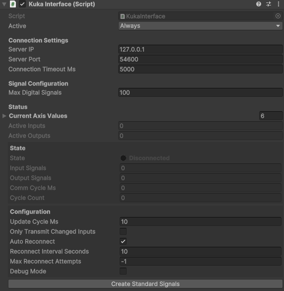
The KUKA interface provides comprehensive configuration options through the Unity Inspector, including connection settings, signal configuration, real-time axis monitoring, and status information.
Properties
Section titled “Properties”Connection Settings
Section titled “Connection Settings”Server IP (string) specifies the IP address of the KUKA Y200 server. Default value is 127.0.0.1 for local connections with KUKA OfficeLite virtual controllers. For real robot controllers or external simulations, enter the controller’s IP address on your network. When using OfficeLite with the OC_Assistant_OfficeLite server, this typically remains 127.0.0.1 for local development.
Server Port (integer) defines the TCP port for Y200 communication. The standard KUKA Y200 port is 54600. This rarely needs to be changed unless your controller is configured for a different port.
Connection Timeout Ms (integer) sets the maximum time in milliseconds to wait for a connection before failing. Default is 5000ms (5 seconds). Increase this value for connections over slower networks or when connecting to busy controllers.
Signal Configuration
Section titled “Signal Configuration”Max Digital Signals (integer) determines how many digital I/O signals to create and manage. The value can range from 1 to 8192 to match KUKA’s $IN and $OUT arrays. Default is 100 for performance optimization. Only create the number of signals you actually need, as processing thousands of unused signals impacts performance.
Status (Read-Only)
Section titled “Status (Read-Only)”Current Axis Values (float array) displays real-time robot axis positions in degrees for axes 1-6. These values are continuously updated from the KUKA controller and can be used to drive robot visualization or monitor robot state.
Active Inputs (integer) shows the count of active input signals (InBool) currently configured and being monitored. This helps verify that signals are properly created and recognized.
Active Outputs (integer) indicates the number of active output signals (OutBool) currently configured and being monitored. Use this to confirm output signal configuration.
State displays the current connection status (Disconnected, Connecting, Connected, or Error). Monitor this to ensure proper communication with the KUKA controller.
Input Signals shows the total number of input signals detected in the interface hierarchy.
Output Signals displays the total number of output signals found in the interface hierarchy.
Comm Cycle Ms indicates the communication cycle time in milliseconds, showing how frequently data is exchanged with the controller.
Cycle Count tracks the total number of successful communication cycles since connection was established.
Configuration
Section titled “Configuration”Update Cycle Ms (integer) sets the communication update interval in milliseconds. Default is 10ms for smooth real-time updates. Increase this value to reduce network traffic or CPU usage.
Only Transmit Changed Inputs (boolean) when enabled, optimizes communication by only sending input values that have changed since the last cycle. This reduces processing overhead for systems with many signals.
Auto Reconnect (boolean) enables automatic reconnection attempts when the connection is lost. Recommended for production systems to maintain connectivity.
Reconnect Interval Seconds (integer) defines how long to wait between reconnection attempts. Default is 10 seconds to avoid overwhelming the controller with connection requests.
Max Reconnect Attempts (integer) limits the number of reconnection attempts before giving up. Set to -1 for unlimited attempts.
Debug Mode (boolean) enables detailed logging of communication activities for troubleshooting connection issues or protocol problems.
Signal Naming Convention
Section titled “Signal Naming Convention”The KUKA interface uses specific signal naming patterns that map to KUKA system variables:
Robot Axes
Section titled “Robot Axes”- Axis1 to Axis6: PLCOutputFloat signals representing robot joint positions in degrees
- These map directly to the robot’s current axis positions
Digital Inputs
Section titled “Digital Inputs”- InBool0 to InBool8191: PLCInputBool signals
- InBool0 maps to KUKA $IN[1]
- InBool8191 maps to KUKA $IN[8192]
- Note the offset: Unity uses 0-based indexing while KUKA uses 1-based
Digital Outputs
Section titled “Digital Outputs”- OutBool0 to OutBool8191: PLCOutputBool signals
- OutBool0 maps to KUKA $OUT[1]
- OutBool8191 maps to KUKA $OUT[8192]
- Same offset applies as with inputs
Basic Setup
Section titled “Basic Setup”- Add the KUKA Interface component to an empty GameObject in your scene
- Configure the connection by setting the Server IP to your KUKA controller’s address:
- For OfficeLite virtual controllers: Use 127.0.0.1 (localhost)
- For real controllers: Use the controller’s network IP address
- Click “Create Standard Signals” button to automatically generate the signal structure
- Enable the interface by checking the Active checkbox
- Monitor the State property to confirm successful connection
Signal Structure
Section titled “Signal Structure”When you click “Create Standard Signals”, the interface automatically creates a organized hierarchy:
KukaInterface├── Axes│ ├── Axis1 (PLCOutputFloat)│ ├── Axis2 (PLCOutputFloat)│ ├── Axis3 (PLCOutputFloat)│ ├── Axis4 (PLCOutputFloat)│ ├── Axis5 (PLCOutputFloat)│ └── Axis6 (PLCOutputFloat)├── Inputs│ ├── InBool0 (PLCInputBool)│ ├── InBool1 (PLCInputBool)│ └── ... (up to MaxDigitalSignals)└── Outputs ├── OutBool0 (PLCOutputBool) ├── OutBool1 (PLCOutputBool) └── ... (up to MaxDigitalSignals)Connecting to Robot Drives
Section titled “Connecting to Robot Drives”To visualize robot movement in Unity:
- Create or import your KUKA robot model in Unity
- Add Drive components to each robot joint
- Enable Follow Position: Set the Drive’s Follow Position property to true so the drive follows external position commands
- Connect the axis signals to your drives:
- Select each Drive component
- In the PLC Output Float field, drag the corresponding Axis signal (e.g., Axis1 for joint 1)
- The drive will now follow the real robot’s position in real-time
Working with Digital I/O
Section titled “Working with Digital I/O”Digital signals can be used for:
- Safety interlocks: Monitor safety gates, emergency stops
- Process control: Trigger grippers, tools, or other equipment
- Status indication: Show robot state, program status, error conditions
Example: Controlling a gripper through KUKA I/O:
- In your KRL program, set $OUT[10] to control the gripper
- In Unity, OutBool9 (remember the offset) will reflect this state
- Connect OutBool9 to your gripper component’s activation signal
Performance Optimization
Section titled “Performance Optimization”For systems with many signals:
- Set Max Digital Signals to only what you need (not the maximum 8192)
- Enable “Only Transmit Changed Inputs” to reduce network traffic
- Increase Update Cycle Ms if real-time response isn’t critical
- Use the signal cache by avoiding dynamic signal creation during runtime
Network Configuration
Section titled “Network Configuration”Ensure proper network setup:
- Firewall rules: Allow TCP port 54600 (or your configured port)
- Network isolation: Keep robot networks separate from general IT networks
- Latency: For best performance, keep Unity and KUKA controller on the same subnet
- Y200 Server: Ensure the Y200 server is running:
- For real controllers: Y200 server must be installed and running
- For OfficeLite: Install and run the OC_Assistant_OfficeLite server
KUKA OfficeLite Integration
Section titled “KUKA OfficeLite Integration”For virtual commissioning without real hardware, you can use KUKA OfficeLite with the OpenCommissioning OC_Assistant_OfficeLite server:
Installing OfficeLite Server
Section titled “Installing OfficeLite Server”- Download KUKA OfficeLite from the KUKA website (requires KUKA account)
- Install OfficeLite following KUKA’s installation guide
- Get OC_Assistant_OfficeLite:
- Clone from GitHub:
git clone https://github.com/OpenCommissioning/OC_Assistant_OfficeLite.git - Or download the latest release from the repository
- Clone from GitHub:
- Install the Y200 server component:
- Navigate to the OC_Assistant_OfficeLite project folder
- Follow the installation instructions in the project README
- The server provides the Y200 protocol interface for OfficeLite
Configuring OfficeLite with realvirtual
Section titled “Configuring OfficeLite with realvirtual”- Start KUKA OfficeLite with your robot project
- Launch OC_Assistant_OfficeLite:
- Run the server application
- Verify it connects to your OfficeLite instance
- Confirm the Y200 server is listening on port 54600
- Configure realvirtual KUKA interface:
- Set Server IP to 127.0.0.1 (localhost)
- Keep default port 54600
- Enable the interface
- Verify connection by checking the State property shows “Connected”
Benefits of OfficeLite Integration
Section titled “Benefits of OfficeLite Integration”- No hardware required: Test and develop without physical robot controllers
- Full KRL support: Run actual robot programs in virtual environment
- Safe testing: Validate programs and sequences without safety risks
- Cost-effective: Develop and commission virtually before hardware arrives
- Multi-robot support: Run multiple virtual controllers simultaneously
- Debugging capabilities: Enhanced debugging compared to real controllers
Troubleshooting
Section titled “Troubleshooting”Common issues and solutions:
Connection fails immediately
- Verify the KUKA controller IP address is correct (127.0.0.1 for OfficeLite)
- Check that Y200 server is running:
- For real controllers: Verify Y200 server installation
- For OfficeLite: Ensure OC_Assistant_OfficeLite is running
- Ensure port 54600 is not blocked by firewalls
- Test network connectivity with ping command
- For OfficeLite: Verify the virtual controller is started and in RUN mode
No axis values updating
- Confirm the robot program is running on the controller
- Check that the Y200 server is configured to send axis data
- Verify signal names match exactly (Axis1, not Axis_1)
Digital I/O not working
- Remember the indexing offset (InBool0 = $IN[1])
- Ensure signals are created with correct names
- Check that I/O is not being overridden by KRL program
- Verify MaxDigitalSignals covers the I/O range you need
Connection drops frequently
- Check network stability and cable connections
- Increase Connection Timeout Ms for unreliable networks
- Enable Auto Reconnect for automatic recovery
- Review controller logs for Y200 server errors
Protocol Details
Section titled “Protocol Details”The Y200 protocol exchanges fixed-size data packets:
From KUKA Controller (1144 bytes):
- Bytes 0-1023: Digital outputs ($OUT array)
- Bytes 1024-1071: Robot axes (6 × 8-byte doubles)
- Bytes 1072-1143: Position/tool/base data (not currently used)
To KUKA Controller (1024 bytes):
- Bytes 0-1023: Digital inputs ($IN array)
This fixed structure ensures predictable, real-time communication suitable for industrial applications.
Integration with realvirtual Components
Section titled “Integration with realvirtual Components”The KUKA interface works seamlessly with other realvirtual components:
Robot Components
Section titled “Robot Components”- Drive: Connect axis signals to drive components for robot visualization
- Robot: Use with the Robot component for complete kinematic simulation
- IK (Inverse Kinematics): Combine with IK for path planning and validation
Signal Processing
Section titled “Signal Processing”- SignalManager: Centrally manage all KUKA signals
- PLCInputFloat/PLCOutputFloat: Extend for analog value exchange
- ValueMapping: Transform signal values for different scaling needs
Automation Logic
Section titled “Automation Logic”- BehaviorGraph: Create visual logic using KUKA I/O signals
- Scripts: Access signals programmatically for custom behaviors
- Sequences: Build complex automation sequences with robot coordination
Best Practices
Section titled “Best Practices”- Signal Organization: Keep the auto-generated folder structure for clarity
- Naming Convention: Follow the standard naming (Axis1-6, InBool, OutBool) for compatibility
- Performance: Only create signals you actually use to minimize overhead
- Error Handling: Implement proper error handling in automation logic for connection failures
- Documentation: Document signal mappings between Unity and KRL programs
- Testing: Test with simulated controllers before connecting to real robots:
- Use KUKA OfficeLite with OC_Assistant_OfficeLite for comprehensive testing
- Validate with KUKA WorkVisual simulation
- Verify all signals and axes before deploying to real hardware
- Safety: Never rely solely on simulation for safety-critical decisions
External Resources
Section titled “External Resources”- OpenCommissioning OC_Assistant_OfficeLite - Y200 server for KUKA OfficeLite integration
- KUKA OfficeLite Documentation - Official KUKA virtual controller documentation
- OpenCommissioning Initiative - Open-source virtual commissioning tools
See Also
Section titled “See Also”- KUKA iiQKA.OS2 VRC (Pro) - For the newer iiQKA.OS2 controller generation via RSI
- Drive - For connecting axis signals to robot joints
- Signal Manager - Managing interface signals
- Signal Importer Exporter - Import and export signal configurations
- Custom Interfaces - Creating custom interfaces