
Fanuc (Pro)
The Fanuc Interface component allows direct communication between Unity and FANUC industrial robots using the SNPX (Robot Interface / SRTP) protocol. It enables real-time control of robot drives, digital and analog I/O, and access to internal robot variables — supporting use cases like digital twins, simulation, and live operation.
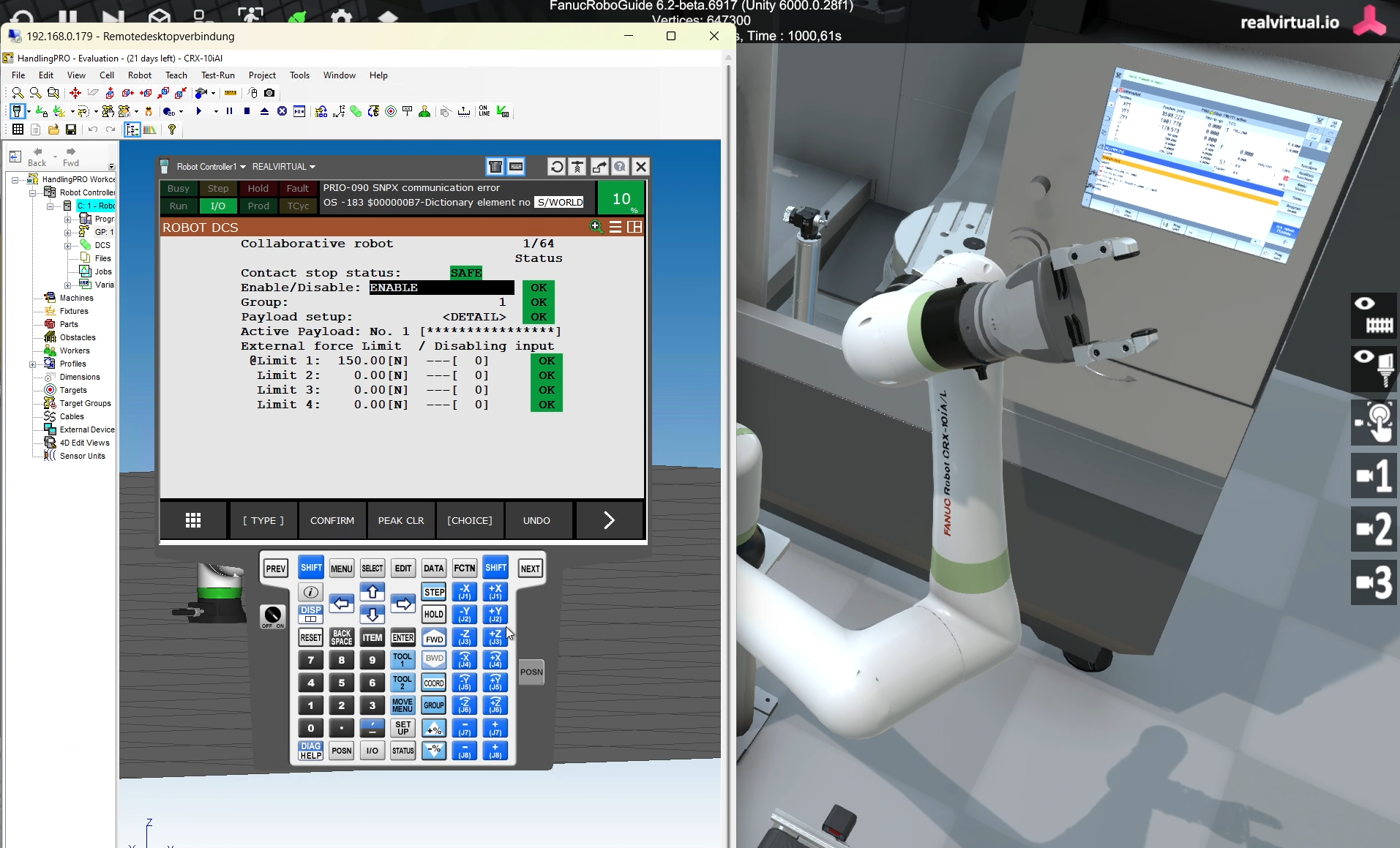
Overview
Section titled “Overview”This interface connects Unity to a FANUC controller over TCP/IP (default port 60008), allowing you to:
- Read/write digital and analog signals
- Track drive and axis positions
Requirements
Section titled “Requirements”To use the SNPX-based communication, your FANUC controller must support the Robot Interface protocol. This can be configured during workcell creation in ROBOGUIDE.
Enabling SNPX
Section titled “Enabling SNPX”You must enable one of the following options when setting up your virtual or physical controller:
- R650 FRA Params:
- Select “FANUC America Corp.” in the Advanced tab of ROBOGUIDE’s Workcell Wizard (Step 7)
- Add option R553 – HMI Device SNPX
- R651 FRL Params:
- Select “FANUC Ltd.” in the same Advanced tab
- No additional options required
Also ensure that:
- TCP port
60008(Robot IF Server) is open and accessible - The controller and Unity application are on the same network or subnet
Inspector Fields
Section titled “Inspector Fields”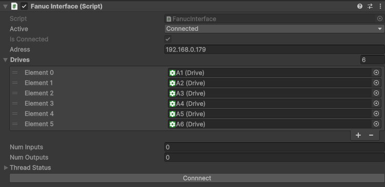
| Field | Description |
|---|---|
| Active | Enables or disables the interface |
| Is Connected | Shows live connection status with the controller |
| Address | IP address of the FANUC robot (e.g., 192.168.0.179). For a ROBOGUIDE virtual robot on the same PC use 127.0.0.1 |
| Port | TCP port of the Robot IF (SNPX) server. Default 60008. In a ROBOGUIDE multi-robot cell each virtual robot uses an incrementing port (robot 1 = 60008, robot 2 = 60009, …) |
| Drives | Assign Unity Drive components to robot axes (supports J1–J9) |
| Num Inputs / Outputs | Displays how many input/output signals are currently active |
| Thread Status | Indicates the state of the background communication thread |
| Connect Button | Triggers the connection process to the controller |
Multiple Robots (ROBOGUIDE Multi-Robot Cell)
Section titled “Multiple Robots (ROBOGUIDE Multi-Robot Cell)”A ROBOGUIDE workcell with several robots on one PC shares a single IP address — each virtual robot gets its own incrementing Robot IF port instead. To simulate such a cell, add one Fanuc Interface per robot and set the Port accordingly:
| Robot | Address | Port |
|---|---|---|
| Robot 1 | 127.0.0.1 | 60008 |
| Robot 2 | 127.0.0.1 | 60009 |
| Robot 3 | 127.0.0.1 | 60010 |
The exact port of each robot is listed in the services.txt file inside the corresponding robot_1, robot_2, … subfolder of your ROBOGUIDE workcell. Assign each robot’s axis Drive components to the Drives list of its own interface, and make sure SNPX (R553 / R651) is enabled on every virtual controller.
Because ROBOGUIDE and Unity run on the same PC, all communication goes over localhost — no network adapter, DHCP or subnet configuration is required. The 192.168.x.x address shown on the teach pendant is ROBOGUIDE-internal and does not need to match a physical adapter.
Signal Mapping
Section titled “Signal Mapping”The Fanuc Interface uses string-based signal names to map FANUC robot I/O into Unity. These names follow a PREFIX + NUMBER format and are parsed automatically on startup.
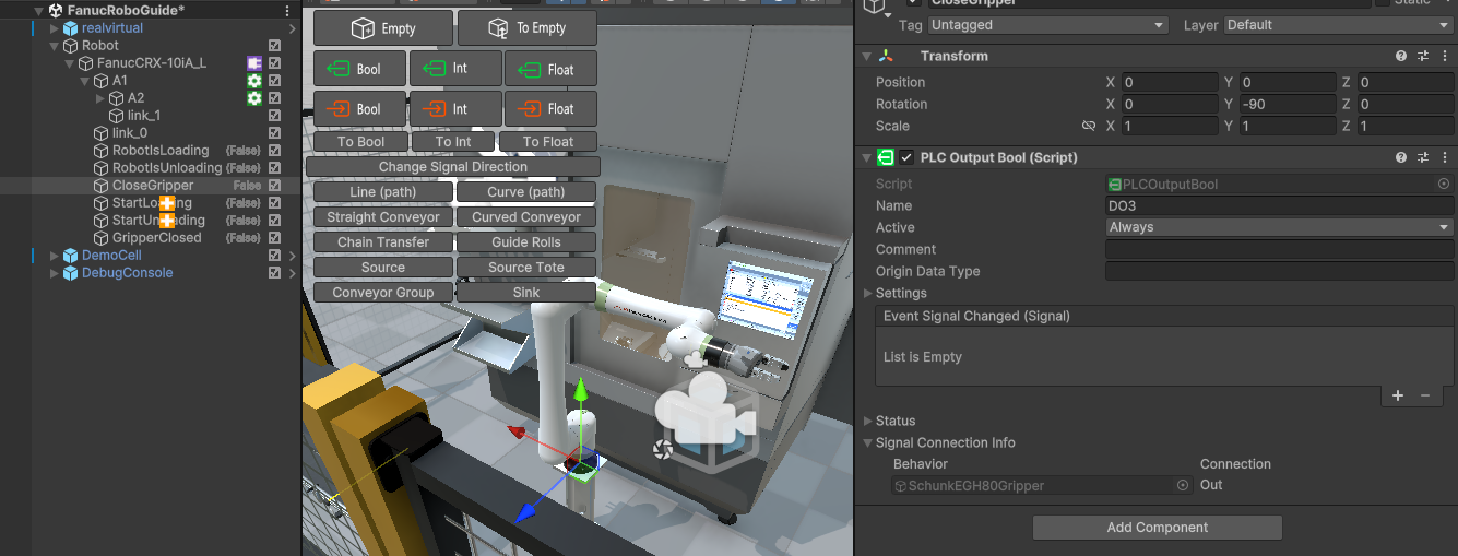
Example of a configured digital output DO3
Supported Signal Prefixes
Section titled “Supported Signal Prefixes”| Prefix | Direction | Description |
|---|---|---|
DI | Input | Device-level digital inputs |
DO | Output | Device-level digital outputs |
UI | Input | User-defined digital inputs |
UO | Output | User-defined digital outputs |
RI | Input | Remote robot digital inputs |
RO | Output | Remote robot digital outputs |
SDI | Input | Safety digital inputs |
SDO | Output | Safety digital outputs |
WI | Input | Welding-specific digital inputs |
WO | Output | Welding-specific digital outputs |
AI | Input | Analog integer inputs (e.g., sensor values) |
AO | Output | Analog integer outputs (e.g., analog actuators) |
Examples:
DO0– Digital Output 0UI5– User Input 5AO3– Analog Output 3WI2– Welding Input 2
Signals are case-insensitive in Unity but are documented here in uppercase for clarity.
See Also
Section titled “See Also”- realvirtual.io Fanuc integration for virtual commissioning – customer story on connecting realvirtual.io to FANUC robots